• Please review our updated Terms and Rules here

IBM 5154 Troubleshooting

If the problem comes and goes then it is most likely a crack in the solder. Look around with a magnifier in the power supply for ring cracks around leads like the big black cap. Just google 'cold solder joint' and you can see good examples.
If you find some then just find someone with a soldering iron and skills to solder it. I used to do CRT service but not anymore.

PS - Or just take good close up well lighted and focused photos. It's amazing what shows up with the modern I-something cameras that the photo can be enlarged. Can share here too.

Larry G
 
Last edited:
Hi folks,

I recently got brave and stripped down my 5154 to do some fault-finding after the magic smoke escaped ...

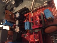
I've repaired the power supply by replacing the two blown X2 line suppression capacitors as seen below:

IMG_1515.jpg

However, now the monitor is suffering from full vertical-collapse.

Assuming something to do with the TDA2653A I replaced this as the old one looked slightly cooked, and also had to replace C303 - the 1000uf capacitor as it had also died.

After doing these, still no success ...

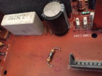
But after tracing back from the TDA I came across a totally fried resistor R323 - which seems to take the brunt of the power from the PSU to the TDA circuitry.

My problem is I can't tell what the correct value of R323 should be as it's completely toast :-/

IMG_1665.jpg

Can someone let me know the correct value of R323 should be as I really don't want to buy the SAMS service guide just for this?

I'm sure when this is replaced the TDA will get power and start functioning normally ...

Thanks for any help!

Stewart
 
Can someone let me know the correct value of R323 should be as I really don't want to buy the SAMS service guide just for this?
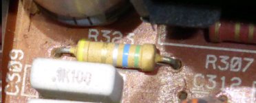
The circuit diagram in the SAMS PhotoFact indicates 0.56 ohm.

An in-circuit measurement of the R323 in my 5154 is 0.7 ohms. So, my R323 must be slightly high in value, and my multimeter is probably doing some rounding (was on the lowest resistance range).

5154_R323.jpg
 
The circuit diagram in the SAMS PhotoFact indicates 0.56 ohm.

An in-circuit measurement of the R323 in my 5154 is 0.7 ohms. So, my R323 must be slightly high in value, and my multimeter is probably doing some rounding (was on the lowest resistance range).

View attachment 30532

Hi, thanks for the info! I'll get this ordered along with some more replacement caps and hopefully bring this monitor back to life :)
 
I am not sure if anyone is still monitoring this thread, but it has been very helpful as I am trying to fix a non-working 5154. I am not seeing anything on the 6.3V rail and I am looking for suggestions for what else to look for. So far I have replaced the electrolytic caps (except for the two really big ones which test fine on an ESR meter), and I have tested all the other transistors, diodes, and resistors. I am doing this testing with the power supply disconnected from the mainboard, but I also tested once with it connected to make sure the voltages on the other rails were correct under load. I have also replaced IC1, just in case it was wonky since the voltages I am measuring there are not quite the same as in the SAMS book.

1) What else could cause the missing 6.3V. What should I test?
2) The SAMS book says it should be -6.3V. Is that true. Is it really negative?
3) I doubt the transformers are bad, but if I wanted to replace them do they still make a similar model? Anyone know the part number? I can't find an FM 490 or FM 492 anywhere online.
4) Could I/Should I just add a separate 6.3V transformer to supply the heater voltage? It wouldn't be very hard, but I am not sure the amperage.
 
I am not sure if anyone is still monitoring this thread, but it has been very helpful as I am trying to fix a non-working 5154. I am not seeing anything on the 6.3V rail and I am looking for suggestions for what else to look for. So far I have replaced the electrolytic caps (except for the two really big ones which test fine on an ESR meter), and I have tested all the other transistors, diodes, and resistors. I am doing this testing with the power supply disconnected from the mainboard, but I also tested once with it connected to make sure the voltages on the other rails were correct under load. I have also replaced IC1, just in case it was wonky since the voltages I am measuring there are not quite the same as in the SAMS book.
Quote: "not quite the same". Explain, ideally with examples. And SAMS would have made their measurements under load, and so that should be the basis of the comparison.

1) What else could cause the missing 6.3V. What should I test?
2) The SAMS book says it should be -6.3V. Is that true. Is it really negative?
The fact that you asked "Is it really negative?" helps informs me, to a degree, of your electrical/electronics knowledge. But then, perhaps you meant, "For a heater, any particular reason why negative?"

On its own, a figure like '-6.3V' will mean -6.3V with respect to (WRT) ground or chassis, or whatever is being used as the reference point in the circuitry for the measurement. The SAMS document tells us that the author is using ground as the reference potential, which is what I expected.

Refer to the diagram at [here]. An important thing to note is that the 5154's power supply unit itself is generating a ground-isolated 6.3V (6.3V being an under-load figure), just like a battery. It is only when the power supply unit is plugged into the main board does that voltage generation then get referenced to ground.

(And because it is the positive side of the generated DC voltage that is being grounded by the main board, then with respect to ground, the generated voltage is negative.)

What this all means that, with the power supply unit detached from the main board, trying to measure the 6.3V with the negative lead of your multimeter connected to ground (or connected to the power supply unit's cage) is not going to work.

If you connect your multimeter's leads across C23, do you measure a DC voltage ?
 
If you connect your multimeter's leads across C23, do you measure a DC voltage ?

Well, low and behold I get 14V across C23 while it is disconnected from the main board which is what I expected! I had replaced C23, a few bad resistors, one bad transistor, and a diode in my troubleshooting but didn't see any voltage because I wasn't measuring it correctly. As you deduced from my question, I was indeed measuring it to chassis ground.

And when I plug it back into the mainboard ...
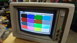
MVIMG_20201126_204459_sm.jpg
Thank you so much for the explanation! I can't believe this is working again.

One more question ... what is the voltage adjust pot on the power supply for? In my testing, I marked it with a sharpie and then moved it slightly to see if any of the voltages changed at all, but they did not. I didn't dare move it too much without knowing how it would affect things on the PS.
 
One more question ... what is the voltage adjust pot on the power supply for? In my testing, I marked it with a sharpie and then moved it slightly to see if any of the voltages changed at all, but they did not. I didn't dare move it too much without knowing how it would affect things on the PS.
'V ADJ' potentiometer (RT1).
In the SAMS document, read the first block on the 'Miscellaneous Adjustments' page.
 
Wow people are still using this 12+ year old thread so I thought I might join in with my problem... I've acquired five 5154s and opened up two to replace the X2 caps in the PSU. Both come up with crazy flickering on the screen when the computer (a Tandy 1000, so CGA signal) and less than ideal image on the screen...

I made a video of one, what do people think?


Does anyone elses do this on the screen when not connected to a computer? Also I don't know if it makes any difference but I'm in Australia so the monitors are 240V...
 
Maybe my post flew under the radar but just wondered if anyone had seen a 5154 with the screen problems mine is showing?

UPDATE: as of now all the e-caps in the PSU have been replaced except for the two large ones (both tested OK still) and the picture is sharp and bright, just wildly out of sync and jumping all over the place when the computer is turned off.

I'm about to proceed to recapping the video processing board and then if it doesn't come good, the main (lower) board..

Fingers crossed.
 
I've acquired five 5154s
Quite a lot.

Does anyone elses do this on the screen when not connected to a computer?
As I am sure you are aware, expected is what is shown at [here].

I made a video of one, what do people think?
Vertical deflection problem.

Done a thorough visual inspection ?

I have fixed various (including 'weird') vertical deflection problems in the 5154 by replacing the TDA2653A chip, but there can be many causes.

Do you have an oscilloscope and the knowledge of how to use it? If so, do you have the SAMS Computerfacts document on the 5154 ?

Also I don't know if it makes any difference but I'm in Australia so the monitors are 240V.
No difference.

If you can deliver (and fetch) the problem monitors to the south eastern suburbs, I will freely look at them in my spare time.
 
Thanks Modem7, that gives me much to go on. Yes I have a scope and soldering rework station, and now with the Sams guide.

I've had a look and the 2653A (if that turns out to be the problem) is available locally and not for very much $.

I plugged in a 3rd one of these yesterday and while the filter caps blew one after the other pretty quickly, the clear white screen was observed this time, so I'm going to focus on that one first and come back to the other two with the obvious deflection probs later.

Cheers,

Ian.
 
Anyone want to help +1 to the pile of repaired 5154s?

A friend recently won an auction for a small haul of IBM stuff, mostly faulty. Among them was a 5154 which they'd bee wanting for ages. I offered to repair as much of the IBM stuff as I could, including the 5154, and got myself a 5151 I wanted and a few other doodads in exchange.

This 5154 has had a lot of hours put in so far, and I am not too sure where to go on yet.

1) RIFA caps in PSU, and the commonly bad small caps had to be replaced for it to fire up.

2) the pots relating to sync and size were all wrong. I got that working for both Mode 1 and Mode 2.

3) someone else had already had a go it seems. The convergence was way off and one of the ring tabs was snapped off. I think they tried to adjust convergence without loosening the main ring. I have re-converged it the best I can. It is still imperfect around the edges. I don't know if that's normal for this monitor (it's still better than my 5153, but my 8513 is perfect). First time I've tried converging a CRT, and I spent a good few hours.

4) Nearly there I think. The problem now is that the image is wobbly on startup for a good few minutes. The wobble get less and less until it looks like a vibration (not seen on camera), until finally, the picture is solid. But after that, it still glitches occasionally, and one time, it even went complete out of focus for a moment before coming back.
This video shows all of that. The out-of-focus event is near the end.

I have replaced all the caps on the video board, and some of them on the main board. The remaining caps for the main board are on their way.
I have applied fresh solder to most of the joints and inspected the rest.
Someone said it may be the tripler. I have found a replacement, but the shipping cost is high, so I would rather rule other things out first.
The FBT has no part number, but that person said the tripler is far more likely to go than the FBT.
 
To add on to my prior reply:
I have just finished replacing the rest of the electrolytic caps in the 5154.
This has solved the wobbly sync when cold. I still occasionally get the bursts of out-of-focus picture, especially when cold. Not sure what to check for next so I may try find a replacement tripler.
 
I identified a 'only when cold' issue on another system by spraying each component with an upside down can of canned air. Maybe not the best for an intermittent problem, but it sure identified the temperature sensitive part quickly.
 
Bursts of out-of-focus *could* be the flyback. Any cracks/leaks or sounds near it?

I don't hear anything odd near the flyback.
The flyback and tripler are separate units on this, unlike most CRTs where they're combined.
I have cleaned the tube neckboard, socket, and fixed some suspicious solder joints there, to no effect.

According to a schematic (Sam's), there are separate horizontal output and high-voltage output transistors. Perhaps the high-voltage output circuit has a problem. I don't have the tools to probe that section however. I could check the power supply though.

Also, I noticed that even though the main wobbly sync issue is gone, there is still a slight one that persists. You can see it in my video here: https://photos.app.goo.gl/i1CeZRKESLTcXuPW9
 
Hello Everyone,
The discussion(s) here have been very helpful; I am trying to resurrect 3 5154's I've had for many years.

Can this discussion continue? Can anyone point to a newer thread on the 5154 subject??

THANKS!
Regards, Terry King
...In The Woods In Vermont
The one who dies with the most Parts LOSES! WHAT DO YOU NEED??
 
The discussion(s) here have been very helpful; I am trying to resurrect 3 5154's I've had for many years.
Are you aware of the hazards inside the 5154 ?
Do you have tools such as a multimeter and an oscilloscope, and the knowledge of how to use them ?
For each 5154, what is the symptom ?
Have you done a good visual inspection within each 5154 ?

For the 5154's that behave as shown at [here] (i.e. mostly working), you will have then connected the 5154 to an EGA video source. Is that a known-good EGA video source ?

Some known problems/issues listed at [here].
 
Back
Top