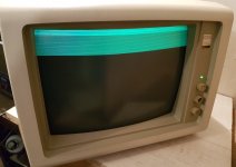
The first video shows an irregular or erratic horizontal position error the displayed text.
With something like this the first question is :
Is it the scanning raster that has the error, or is it the timing of the picture information that has it.
Often, initially, it can be difficult to tell because the CRT is over-scanned and the edge (sides) of the scanning raster is not visible, unless say the width was reduced and the brightness turned up to see the right or left hand edge of the raster.
In general irregular horizontal raster scan defects occur because the peak yoke scanning currents are very high at the beginning and end of scan, so bad connections, dry solder joins etc can be a cause.
If it is the picture (video) content moving in the raster (and the scanning raster is rock solid) this implies a fault in the H sync and AFC circuit and even the H scan oscillator circuit.
If there is amplitude modulation of the H sync (say from power supply ripple), it causes phase errors that can do it.
If the oscillator frequency is moving around that can also do it.
The reason is that the Horizontal lock system (called AFC or automatic frequency control) is a type of PLL (phased lock loop) where the output frequency is fed back, compared with the H sync pulse frequency and a DC control voltage is created which manipulates the running frequency of the H scan oscillator to pull it into phase lock with the incoming H sync. Any disturbance inside the AFC loop, from any cause will make the picture shift left and right or jitter. This is why once the system is in lock, if you turn the H. hold control, this way and that, the picture will move left and right before it drops out of lock. Many sets also have a phase control, to set the H picture position which either manipulates the arrival time of the sync or the fed back oscillator output signal.
And of course if there are power supply problems you can have simultaneous picture disturbances along with raster disturbances.
In cases where there is trouble in the AFC loop, the only way to see of the H.osc and other parts are stable is to remove the H sync pulses (or break the loop) and watch the picture float by horizontally and see if the crawl rate looks stable or has a jitter on it. As I recall in the 5153 at least, if the H sync coupling capacitor is disconnected (removed from the board) from the H scan processor IC, there is still just enough sync coupling by stray capacitance for the H scan oscillator to barely lock, and this is a method by which the correct setting of the H oscillators hold control(the free running H scan frequency can be made) and the the phase control adjusted after that once the capacitor is re-inserted.
If you read page 30 to 32, section 6 of this article (about the AFC in the 5153, which is essentially the same as in the 5154 and all color VDU's) it explains it better than I can here in a post:
As noted in the text there can be combinations of setting of the H hold and H phase controls that might look ok on the screen, but they would be less stable than when the correct combination is present.
Likely though, out of all the things that could be wrong, the power supply stability is in question, so it needs to be examined with the scope.
It will be interesting to see if the replacement 270pF capacitor helps or not.
 drive.google.com