• Please review our updated Terms and Rules here

IBM 5161 Extender card not working

detscadosu24

Member
Joined
Aug 17, 2023
Messages
21
Hello,
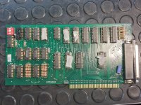
I built myself an extender card using these files: https://github.com/schlae/ibm-extender
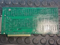
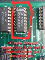
I now put it inside my 5160 and on boot the card is completely ignored. No 1801 error even if the expansion unit is disconnected, and if connected it does not work. I tested all ICs except one, see pictures.
Did anyone encounter the same problem?
Thank you20230817_175905.jpg20230817_175913.jpg20230817_175944.jpg20230817_180209.jpg
 
I do not think the resistor networks (RN1, RN2 and RN3) can be replaced with discreet (isolated) resistors the way you have them.

A quick check of the BOM gives Mouser part numbers 652-4116R-2LF-4.7K and 652-4116R-2LF-10K. The Mouser part numbers map to 4116R-2-472LF and 4116R-2-103LF respectively. These parts share the same datasheet here. Decoding the manufactures part number indicates these are bussed resistors, the 2 for Electrical Configuration tells us this.

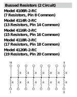
This snippet from the datasheet shows what the expected network looks like.

resistor-network-configuration.png

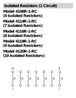
The discreet resistors installed as shown look more like this snippet from the datasheet.
discreet-configuration.png
With a bit of wire and a few more resistors one could build up the networked configuration.
 
you can check the 74ls155 chip easy enough. Just hook it to a breadboard, give 5v for power and for a few high pins. gnd for some low pins and check the output pins against the truth table:


If you don't have a breadboard and a little power supply (a usb power supply would be sufficient) I highly recommend it! A little kit like this in a baggy (and don't forget the multimeter of course, or otherwise you'll need to use the LEDs in line with a resistor as indicators) is more than enough for tons of this type of testing https://www.amazon.com/REXQualis-Electronics-Breadboard-Resistor-Raspberry/dp/B078XV3RK2/
 
I do not think the resistor networks (RN1, RN2 and RN3) can be replaced with discreet (isolated) resistors the way you have them.

A quick check of the BOM gives Mouser part numbers 652-4116R-2LF-4.7K and 652-4116R-2LF-10K. The Mouser part numbers map to 4116R-2-472LF and 4116R-2-103LF respectively. These parts share the same datasheet here. Decoding the manufactures part number indicates these are bussed resistors, the 2 for Electrical Configuration tells us this.

This snippet from the datasheet shows what the expected network looks like.

View attachment 1262677

The discreet resistors installed as shown look more like this snippet from the datasheet.
View attachment 1262679
With a bit of wire and a few more resistors one could build up the networked configuration.
Thank you! I will buy the parts from Mouser and update this thread once I have them on hand.
you can check the 74ls155 chip easy enough. Just hook it to a breadboard, give 5v for power and for a few high pins. gnd for some low pins and check the output pins against the truth table:


If you don't have a breadboard and a little power supply (a usb power supply would be sufficient) I highly recommend it! A little kit like this in a baggy (and don't forget the multimeter of course, or otherwise you'll need to use the LEDs in line with a resistor as indicators) is more than enough for tons of this type of testing https://www.amazon.com/REXQualis-Electronics-Breadboard-Resistor-Raspberry/dp/B078XV3RK2/
I already have everything, I will test this one as well. Thank you :)
 
Back
Top