• Please review our updated Terms and Rules here

IBM 8513 Monitor width

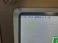
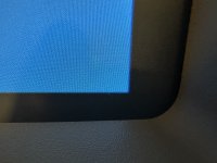
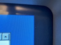
Hi, it’s me again. The monitor seems ok except one small issue in the left top corner, it is not even, you can see in the photos, one is ok from the other similar monitor and the other pretty obvious is from this one, it is bowed outwards. I also included all other corners, they’re ok.

And it was like that from the start, before I started to mess with it, with old FBT, and now with the new one.

Both pcc controls can’t make it straight, even when screen looks like a pillow, top left corner still does that.

I bought a scope, what should I look into? In my very limited understanding when the ray starts to scan new screen something let it slip a bit farther then it should and then normalizes. Probably something that I can replace?
 

Attachments

  • IMG_3022.jpeg
    IMG_3022.jpeg
    4.3 MB · Views: 10
  • IMG_3039.jpeg
    IMG_3039.jpeg
    4.2 MB · Views: 11
  • IMG_3042.jpeg
    IMG_3042.jpeg
    2.8 MB · Views: 10
  • IMG_3041.jpeg
    IMG_3041.jpeg
    3.2 MB · Views: 8
  • IMG_3040.jpeg
    IMG_3040.jpeg
    3.1 MB · Views: 8
Last edited:
The thing is to determine if it is a gradual curvature of the side of the raster, or if it is just the local area and one corner. In the case of the gradual curve in or out, similar on the left and R hand sides, this is adjusted by the east west modulator circuit and there are presets there for that.

If it is just one corner, or the effect is just local to the corner, this is the raster scan geometry, which is calibrated at the factory with magnets around the perimeter of the deflection yoke, close to the bulb (Not the magnetic rings on the neck). These magnets sometimes were on a stalk so you could rotate them, other times they are glued in or captured in the plastic of the Yoke perimeter near its largest diameter. Many color CRT's were supplied with the yoke attached and these magnets were set up for the best possible rectangular raster scan at the factory. Sometimes, even on new sets, it is never perfect in the 4 corners.
 
Interesting, there were some round magnets about half an inch (12mm) diameter under some scotch tape on the tube, on the wide part.
And yes, it is always only left top corner.
 
The magnets on the CRT are usually to correct color purity errors in the corners.

The pictures you show look fine to me. These things were never perfect, even when new. It's one of the things that tended to be better (but still not perfect) on high priced monitors, compared to cheaper models. The 8513 with a basic monitor in its day. We're so used to the perfect geometry on flat panels that we forget how imperfect CRTs were.

You may want to try finding a better compromise among the four corners with the PCC controls.
 
Back
Top