• Please review our updated Terms and Rules here

IBM Enhanced Memory Expansion Adapter -- Bad Tantalums?

lyonadmiral

Veteran Member
Joined
Jun 3, 2009
Messages
2,431
Location
Peru, New York
Picked up recently one of these adapters, just came in tonight, pulled the AT out of its tower enclosure and what I discovered is system will not turn on with the card installed. As with the CGA card that will cause the same issue with a bad tantalum, could that be what the issue is here? Has anyone also experienced it and if not, once I get my volt meter what should I look for?
 
Picked up recently one of these adapters, just came in tonight, pulled the AT out of its tower enclosure and what I discovered is system will not turn on with the card installed.
By "not turn on", I will assume that the power supply does not operate (i.e. power supply overloaded).

As with the CGA card that will cause the same issue with a bad tantalum, could that be what the issue is here?
Certainly, but there are many components that can go faulty in a way that overloads the power supply.
But the probability is high that it is a tantalum capacitor.

... and if not, once I get my volt meter what should I look for?
You could use a meter to narrow down which is the affected voltage rail/line (e.g. +5V or -5V or +12V or -12V), and continue from there, knowing that the scope of circuitry to investigate is now lower.

But, given the tantalum probability, I think that you should take a punt:

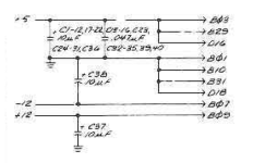
The technical reference for the card is at [here]. Within that, the circuit diagram is in section 6. The circuit diagram shows many capacitors, as shown below, and reveals that the card uses +5V, -12V, and +12V.

If there is a short-circuit tantalum capacitor, it is most likely to be one on the -12V or +12V rail/line. And so I suggest that you simply remove both (perhaps one at a time) and then see if the power supply operates. "C38" is clear enough, but is the other "C57" ?

1697077283232.png
 
I can't find a C57, possible a 37?
I think you are right.

Looking at the partial circuit diagram in post #2, I see the following, and the cap in question 'fits' into the missing C37 spot.
"C1-12"
"C13-16" (assumed C13)
"C17-22"
"C23"
"C24-31"
"C32-35"
"C36"

"C38"
",39"
",40"
 
I snipped off the C38 which was a three pin tantalum, no change in power on. I can't get to the C37, it's packed too tightly amidst some other surface mount stuff and my soldering iron is not precision enough to get it off that way.
 
I snipped off the C38 which was a three pin tantalum, no change in power on. I can't get to the C37, it's packed too tightly amidst some other surface mount stuff and my soldering iron is not precision enough to get it off that way.
You could try 'crush destruction' using long-nose pliers until you see three wires sticking up out of the PCB.
 
At this stage, if you want to see if there is a short-circuit:

1. Refer to the photo at [here].
2. Put your multimeter into resistance mode (not continuity mode).
3. With card out, measure between the ground pin and the +12V pin. A short-circuit would be indicated by zero ohms, or up to, say, a few ohms.
4. With card out, measure between the ground pin and the -12V pin. A short-circuit would be indicated by zero ohms, or up to, say, a few ohms.
5. With card out, measure between the ground pin and the first +5V pin. A short-circuit would be indicated by zero ohms, or up to, say, a few ohms.
6. With card out, measure between the ground pin and the second +5V pin. A short-circuit would be indicated by zero ohms, or up to, say, a few ohms.
7. With card out, measure between the ground pin and the -5V pin. A short-circuit would be indicated by zero ohms, or up to, say, a few ohms.

Both +5V pins need to be tested. I have encountered cards where the two pins are not connected.

If we believe IBM's circuit diagram, then step 7 is not required.
 
Like the ceramic capacitor highlighted in the photo at [here] ?
This is what I've done so far...
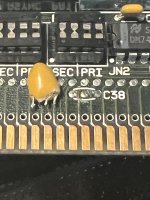
This is C38...
IMG_4487.jpg
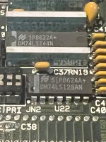
This is where C37 is...
IMG_4485.jpg
I don't have my multimeter with me, it's a cheap one and not sure if it has a resistance mode. Shows how ignorant I am at this level, but I'll find out.
 
This is where C37 is...
Hmm. That certainly looks like a ceramic to me. I expect the 10 µF caps on the +12V line and -12V lines to be identical.

I don't have my multimeter with me, it's a cheap one and not sure if it has a resistance mode.
It will. A multimeter without a resistance mode is like pizza without cheese.
 
A multimeter without a resistance mode is like pizza without cheese.
A friend of mine is lactose intolerant and will occasionally order a pizza without cheese. He let me know that if you order a pizza, online, and choose no cheese that they will definitely call you and make sure that it wasn’t an accident.
 
Test Results:
Pin 1 Ground and Pin 3 (+5) = .881
Pin 1 Ground and Pin 5 (-5) = .0L
Pin 1 Ground and Pin 7 (-12) = .000
Pin 1 Ground and Pin 9 (+12) = 1.760
Pin 31 Ground and Pin 29 (+5) = .881
 
Test Results:
Pin 1 Ground and Pin 3 (+5) = .881
Pin 1 Ground and Pin 5 (-5) = .0L
Pin 1 Ground and Pin 7 (-12) = .000
Pin 1 Ground and Pin 9 (+12) = 1.760
Pin 31 Ground and Pin 29 (+5) = .881
Because your meter is set to the 2K ohm (0 to 2 K ohm) range:

+5 = 881 ohms
-5 = {really really high}
-12 = something near 0 ohms <--- this will be the problem
+12 = 1.76K ohms

As for the -12V, do that measurement again but with the meter in 200 ohm mode (0 to 200 ohms) mode. That will give a better reading.
 
If I put the meter in 200 ohm mode the display goes to OL which according to the manual means overrange indication. It will stay on OL no matter which set of pins I measure.

Just to verify I am testing right; negative goes on ground and positive goes on each other pin?

If this makes any difference the manual mentions that the range is 200 ohm but the resolution is 0.1 ohm... For 2K ohm the resolution is 1 ohm.
 
If I put the meter in 200 ohm mode the display goes to OL which according to the manual means overrange indication. It will stay on OL no matter which set of pins I measure.
That is expected for the +5/-5/+12 measurements because they are all over 200 ohms.

But not for the -12V measurement. You measured .000 in 2K ohm mode. (.000 x 2K ohm = 0 ohm)

Just to verify I am testing right; negative goes on ground and positive goes on each other pin?
Unimportant in resistance mode.

If this makes any difference the manual mentions that the range is 200 ohm but the resolution is 0.1 ohm... For 2K ohm the resolution is 1 ohm.
Reducing the range (e.g. 200K to 200) is normally what one does to improve the accuracy and resolution. Accuracy and resolution are distinct, but related.

Because the resolution is 0.1 ohm in 200 ohm mode, expected accuracy is +/- 1 ohm. And that kind of accuracy is what we are after here because of what is to be done next in determining which cap is on the -12V line.

In 200 ohm mode, try again a measurement of the -12V line. Maybe you were one pin out on the edge connector.
 
In 200 ohm mode, try again a measurement of the -12V line. Maybe you were one pin out on the edge connector.

Assuming that you remeasure, and see 0 to a few ohms:

That confirms that the problem is on the -12V line.

Now to identify the 10 µF cap on the -12V line.

Assumption: There is only one cap on the -12V line, and it is short-circuit, and its resistance is 0 to a few ohms.

"C37" in the circuit diagram surely is wrong.

With your meter in the 200 ohm mode, put one probe on the -12V pin of the edge connector, and in turn, move the other probe between the various caps on the card.

Start with the larger sized caps. When on a cap, move the probe between all pins.

At some point, the measurement will be '0 to a few ohms' for all pins on the cap, and when you do, that is the cap on the -12V line.

FYI: The '0 to a few ohms' measured is either:
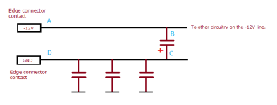
- Points A to B in in the diagram that follows - the resistance of the copper trace running between points A and B .
- Points A to C in in the diagram that follows - the resistance of the copper trace running between points A and B plus the resistance of the short-circuit cap.

1697321639917.png
 
When I measured again it did come up as 0.00 versus OL.

In 200 ohm mode it all shows up as OL. I'm putting positive probe on pin 7 (-12) and putting negative probe on each pin of the tantalum's on the solder side... what I'm discovering is outer pin's show up as 0.00 but inner pin shows up as (for example C17) .756
 
Last edited:
In 200 ohm mode, try again a measurement of the -12V line. Maybe you were one pin out on the edge connector.
When I measured again it did come up as 0.00 versus OL.
As I expected.

Am I still putting one probe on the -12 on the solder side of the board and trying to probe the component side?
You will be referring now to post #18.

On the edge connectors, -12V only appears on the solder side. But if you can find -12V on the component side of the card somewhere, that is valid too.

As for the other probe, the one being used on caps, you can probe on either the solder side or the component side. Up to you.
 
Back
Top