Ruud
Veteran Member
I own a LabProg+ and a TL866. Nice programmers but when it comes to testing ICs, I run into problems. So I thought of designing my own 40-pin tester. The core are five 8255s, each good for testing 8 pins. My personal idea is to place them on a ISA board so one of my older PCs can be used to test the ICs. But I'm also thinking about using an Arduino to control the 8255s.

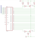
I'm familiar with transistors but not in a totem-pole construction as used here. The first question is, could this work? If I activate Q1, would the resulting voltage at its collector be near +5 Volt? And the same for Q9, would the resulting voltage at its collector be near GND = 0 Volt?
After a reset, all pins of the 8255 start as inputs. An open input can "output" a voltage > 2.5 Volt. But I think that R33 takes care of pulling the input for R1 high enough so Q1 won't be activated. I also think that R3/R4 are good enough for not activating Q9. But "thinking" is not the same as "knowing for sure". Any advice is welcome!
Any advice on the values of the resistors is welcome as well.
It also can be that a pull-down resistor at PC7 is desired as well. If so, I would like to hear from you.
I know there is no protection against a shortage in this design except some fuses you don't see yet. My only protection is careful programming.
Thank you very much in advance!
