• Please review our updated Terms and Rules here

Inboard 386/PC 2mb expansion CLONE

I'm working on a brief instruction manual now. The most important part is to solder those headers while in the inboard. Gold star for anyone that can locate a 40 positinon version of that header! @chjmartin2 are you able to desolder them? Worst-case you can ship it to me and I will repair it if you don't have a de-soldering gun..
 
If you need a manual I can help, I have over 20 years prepress experience and draw lineart/create interchanges for car parts catalogs for years. Well before actual pictures took over... Created 1000s of instruction manuals in the past.
 
If you need a manual I can help, I have over 20 years prepress experience and draw lineart/create interchanges for car parts catalogs for years. Well before actual pictures took over... Created 1000s of instruction manuals in the past.
Thank you! I will reach out if I need some help!
 
@stynx & @harrison.frazier can I get whatever files either of you have I'd like to give this a shot.

Acutally I suspect orienting the ram 90s degrees would work better since each data line would be more equidistanct to the connectors although this may or may not be less convenient to route.

Also since the links got messed up here is a link to the old thread: https://forum.vcfed.org/index.php?threads/seeking-memory-card-for-inboard-386.45638/

The only issue with rotating the simms 90 deg is that their height will block other cards- they are furthest forward so that you can fit as long a card as possible in the next slot (FDC in my case)

:)

IMG_4524.JPG
 
Or are you using standard pin headers?

You need the machined headers as they are a round hole standard pin headers don’t work for this.. the type are listed on the BOM in this forum.
No I messed up.... I am not using the machined headers, so will buy some!
 
The only issue with rotating the simms 90 deg is that their height will block other cards- they are furthest forward so that you can fit as long a card as possible in the next slot (FDC in my case)

:)

View attachment 1252827
Are you running a Cyrix 25/50 486? I have same one. What oscillator are you able to use? I can only seem to get 40 MHz to work.
 
I'm working on a brief instruction manual now. The most important part is to solder those headers while in the inboard. Gold star for anyone that can locate a 40 positinon version of that header! @chjmartin2 are you able to desolder them? Worst-case you can ship it to me and I will repair it if you don't have a de-soldering gun..
I have a desoldering gun. I already had to take them out once because I put them in backwards. I will solder them in when in the card this time. New headers should be here today.
 
Are you running a Cyrix 25/50 486? I have same one. What oscillator are you able to use? I can only seem to get 40 MHz to work.
Yes! I haven't swapped out an osc yet but I plan to, what 40mhz osc did you use? Going to order one. Also might use my flir camera to spot hot ships and add some adhesive heatsinks.
I have a desoldering gun. I already had to take them out once because I put them in backwards. I will solder them in when in the card this time. New headers should be here today.
Crisis averted! Be sure to mate the inboard to the mem module and solder while inserted! :)
 
Annnnnd…. SOS sound from
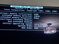
InBoard. My first guess is that I have 1 Meg RAM modules instead of 512K, so now I buy those and go from there. It isn’t impossible that I damaged the board with having to desolder twice, but we shall see.
 

Attachments

  • 65E9CEA1-B457-422F-97DE-75DD714BD944.png
    65E9CEA1-B457-422F-97DE-75DD714BD944.png
    1 MB · Views: 9
Didn’t disable conventional memory on the mainboard or you left another card topping up the system board to 640kb.. doesn’t play nice with other ram cards..
Nope. It runs fine without the ram board and runs fine with my 1 mb board. So has to be something else. My main board only has 256k.
 
Nope. It runs fine without the ram board and runs fine with my 1 mb board. So has to be something else. My main board only has 256k.
Sad times! Could be the ram? Check IC’s are in the right sockets? Frustrating troubleshooting time. Maybe check those pins for any solder bridges ?
 
Sad times! Could be the ram? Check IC’s are in the right sockets? Frustrating troubleshooting time. Maybe check those pins for any solder bridges ?
It is sad times. I reflowed all of the solder that looked suspect. Again - I am using 1 Meg chips instead of 512k - so that could be it.
 
Yes! I haven't swapped out an osc yet but I plan to, what 40mhz osc did you use? Going to order one. Also might use my flir camera to spot hot ships and add some adhesive heatsinks.

Crisis averted! Be sure to mate the inboard to the mem module and solder while inserted! :)

I got it soldered but like I posted - I get the SOS beeps from the computer. Real bummer and not sure how to debug. I am wondering if I messed up a trace with my multiple desoldering. Any recos on metering it out? Is there a circuit diagram available?

Insofar as an oscillator - get yourself a socket and a 4 pin osc and have at it. I have seen people say they have 44 MHZ (or 46 MHz) but I am only working at 40 MHz and if you are running a 2X clock multiplier it makes a big difference.

Thanks, and that is darned frustrating. I DM'ed you the pinout. Theres also some useful info on page 1 of this post. Does it post if you have everything out, including the 7400 logic ICs? It's a 4-layer board with a power and ground plane, and the majority of the logic traces are on the surface. Maybe there was some damage done to the pin header connections on the board as a result of removing them? I am not sure what all scenarios would cause the SOS beep to sound.
 
@peterfleeman @sbenting @cb88
All, sorry for not seeing these sooner. I put the project on hold when I moved last year and haven't worked on it recently. I have ordered 5 more prototype boards, DM me if you want one.

Here's the BOM for this current revision:

4x dual-simm sockets (will need to snip off plastic pins on bottom to fit proto board) found here:

2x 74F02N Quad 2 Input NOR Gate
2x 74F04N HEX Inverters
2x 74F32N Quad 2 Input OR Gate
8x 512K 70-80ns parity simm modules
You may be able to make it work with larger simms, though no guarantees.

Digi-Key part list - Copy the below to a CSV and import:
Index,Manufacturer Part Number,Manufacturer Name,Description,Attrition %,Requested Quantity 1,Pack Quantity 1,Pack Type 1,Digi-Key Part Number 1,Unit Price 1,Extended Price 1,Minimum Order Quantity 1,Customer Reference
1,BDL-110-G-F,Samtec Inc.,CONN HEADER VERT 20POS 2.54MM,,4,4,Tube,SAM10910-ND,11.59000,$46.36,1,"PL1, PL2"
2,110-44-314-41-001000,Mill-Max Manufacturing Corp.,CONN IC DIP SOCKET 14POS TIN,,4,4,Tube,ED90049-ND,0.75000,$3.00,1,V1-V4
3,C315C104M5U5TA7303,KEMET,CAP CER 0.1UF 50V Z5U RADIAL,,4,4,Cut Tape (CT),399-9859-1-ND,0.23000,$0.92,1,C1-C4
4,UMP1A100MDD,Nichicon,CAP ALUM 10UF 20% 10V RADIAL,,2,2,Bulk,493-15546-ND,0.47000,$0.94,1,"C5, C6"
5,CFR-25JB-52-2R,YAGEO,RES 2 OHM 5% 1/4W AXIAL,,18,18,Bulk,2.0QBK-ND,0.06700,$1.21,1,R1-R18

Error on this parts list - Change 74F02N to 74F04N. Not sure how that mistake made it in there!
 
Back
Top