• Please review our updated Terms and Rules here

Intermittent CBM 8032 Power on Issue

Been busy this morning...

Right, we need to check the other side of the full-wave bridge rectifier CR2 now...

Again, using your diode test setting:

J8/1+ to J10/1-
J10/1+ to J8/1-

J8/5+ to J10/1-
J10/1+ to J8/5-

Dave
 
The bridge rectifier looks to be fine.

If you look at the wiring connected to the external capacitor side of J8 you should observe two wires (red) one from J8/2 and the other from J8/4 going to the positive (+) side of the big external capacitor.

Can you see this on your machine?

The positive voltage 'leaves' from J8/4, is smoothed by the external capacitor and 'enters' into J8/2. The +5V regulators are then supplied via J8/2.

Dave
 
Yes I see that. As I mentioned earlier in the thread I have connected a 4032 board and it has performed with no issues. The 4032 and 8032 boards are actually the same universal board version.
 
Ah, so is your 8032 a universal or universal2?

What I suggest you do next is to disconnect the (red) wire from the external capacitor positive terminal that is connected to J8/2 (leaving the wire to J8/4), power up the machine, and measure the DC voltage across the external capacitor.

This should read circa 9V DC.

Dave
 
To be honest I’m not sure which one they are, as both show 8032090 in the silkscreen. I always believed that the SuperPet used the universal 2 board. There is no bodge wire on the underside of the board.
I will check the capacitor which will require me to remove it from the mount. I will report back.
 
Darn...

Well, the next thing I would check is the capacitor itself.

With J8 disconnected, measure the resistance across the capacitor terminals. If you have a cheap and cheerful analogue meter, I would use that.

The resistance should start off LOW and increase as the capacitor charges. Eventually, it will become a very high resistance.

Reverse the meter probes on the capacitor. The resistance should indicate 'negative' and increase as time passes again to a high value.

Dave
 
Yes, the capacitor behaves exactly the way you describe. I also checked another spare cap of the same type and it also behaves in the same way., using the cheap and cheerful analogue meter 😁
 
OK. Onwards and upwards...

So, the next thing is the diode between J8 pins 2 and 3 (CR3).

Can you do a diode test on the following please:

J8/2+ and J8/3-
J8/3+ and J8/2-

This will also have a few other components in parallel with the diode...

Dave
 
You can tell the Universal and Universal 2 apart by looking at the number of TO5 voltage regulators bolted onto the heatsink.

The Universal has 3 whilst the Universal 2 has 2...

Dave
 
Nothing that I can see untoward there.

Ok, can you plug J8 back in and connect up the capacitor.

Power up and read the DC voltage across the terminals of the external capacitor again.

I assume you have nothing connected to the PET's cassette ports?

Dave
 
Ok, so we are getting consistent results.

So that MUST mean that the problem in on the board as opposed to off it.

We either have a bad solder joint on either J8 or the bridge rectifier or there is a high current flowing that is pulling the voltage down.

Let me think about this one...

I would try and measure the AC voltage directly from the transformer connected to J8 pins (1 and 3) and (5 and 3) and see if the voltage collapses when the board is connected. If it does, there is a high current flowing and the voltage is collapsing.

The other possibility is that a component is breaking down when voltage is applied to it.

Just out of interest, do you have the +12V and -5V rails reading correctly? I.e. is the problem related to just +5V?

Dave
 
Last edited:
If the voltage was being pulled down to around 2 V, due to current shunting, something would be smoking.

Probably there is a high resistance connection in the connector or the soldering around the connector pins or diodes.

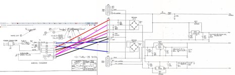
It would be really helpful if the circuit of the transformer/external capacitor was posted along with the regulator/diode wiring diagram of the pcb. On my PET at least, there are two wires returning to the pcb from the capacitor's + terminal and they are required to complete the circuit, but I have no idea if this PET is the same.

I have attached a diagram, possibly right for this PET, but this wiring needs to be correctly documented and posted before fault finding can proceed. The OP should always do this to help others help him/her.
 

Attachments

  • PetPower.jpg
    PetPower.jpg
    163 KB · Views: 8
Last edited:
Back
Top