deanimator
Experienced Member
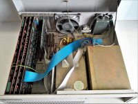
An addendum to romanon's topic from almost ten years ago, avoiding thread necromancy and adding some technical quirks and details: one of the PC/XTs from Czechoslovakia, the Tesla SMEP PP 06, produced between 1986 to around 1990. With the Western embargo having eased up a little, it was evident the PC was here to stay. But to save on the precious hard currency, the commies decided not to purchase PC/compatibles from the West as whole. With the cheap cost of labor, engineers were tasked to counterfeit the XT, so that factories and cooperatives producing farm equipment could do it locally.
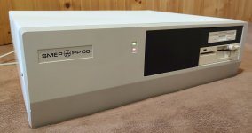
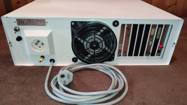
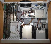
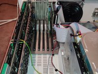
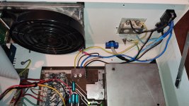
And so we have this absolute behemoth of a PC: 21" x 18" x 7", 45 lbs, in freedom units. The whole case looks like an old breaker box, with the screw terminals and a big receptacle in the back. The paint job and wiring is not original, as I obtained it in a sorry state with bits and chips flaking off, wires chewed and almost everything missing. For this reason, the high density floppies and the SCSI drives were my addition - they're also not stock, sadly. I believe the original drive was a Seagate MFM coupled with two Polish 360K drives.
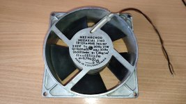
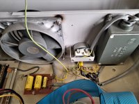
This is the case fan.... original. 220 volt, 21 watt, 50 liters per second of air throughput. This exact type was mounted in stove range hoods and toilet exhausts, but I got lucky this time - it has plastic fins instead of metal. Its noise drowns 2 hard drives, then the worn bearings kick in.
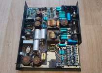
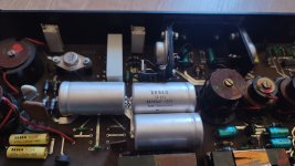
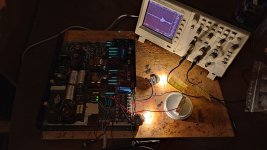
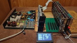
Power supply. Basically 2 identical flyback topologies (the switching element in each is an East German SU160 in TO-3), one for +5 volts and the other for +12. A separate secondary winding on each transformer is kept floating, then rectified, filtered and fed to a 78xx regulator, with its output positive pole sharing common ground, to get -5 and -12 volts in the end. Trimpots on top adjust the feedback loop for output voltage and maximum current. Funny thing is that even though this PSU is current limited, it does not shut down on short circuit. Thus, failing components do so with visual and sound effects, including all traces that led to them. Also, someone before me adjusted the max current of 12 volts (rated at 6A) to well over 13 amps. The power supply survived and keeps on cranking.
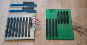
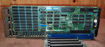
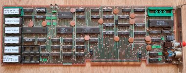
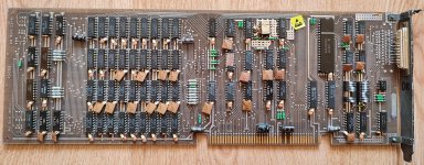
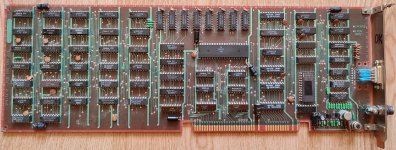
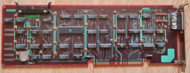
The passive backplane for the system and expansion cards; the original revision on the left has eight 2x43pin card edge connectors. All 8-bit ISA bus signals are present, but the pinout is different - the rest of the signals are either reserved or unused (such as power good, card select or memory size bits). Later revisions of the backplane were of the right-hand style. The basic computer configuration was shipped containing 4 system cards: CPU, RAM+RS232, video (CGA and later Hercules) and a floppy+LPT card. All of these are taller and longer than a full height PC ISA card, and so the ISA card adapters also act as "risers". Pictured above is a modern recreation from a far eastern PCB foundry.
I presume the reason why they did it like this was unreliability (for faster card switchovers) and avoiding complexity, instead of having it all on a single mainboard.


And so we have this absolute behemoth of a PC: 21" x 18" x 7", 45 lbs, in freedom units. The whole case looks like an old breaker box, with the screw terminals and a big receptacle in the back. The paint job and wiring is not original, as I obtained it in a sorry state with bits and chips flaking off, wires chewed and almost everything missing. For this reason, the high density floppies and the SCSI drives were my addition - they're also not stock, sadly. I believe the original drive was a Seagate MFM coupled with two Polish 360K drives.

This is the case fan.... original. 220 volt, 21 watt, 50 liters per second of air throughput. This exact type was mounted in stove range hoods and toilet exhausts, but I got lucky this time - it has plastic fins instead of metal. Its noise drowns 2 hard drives, then the worn bearings kick in.


Power supply. Basically 2 identical flyback topologies (the switching element in each is an East German SU160 in TO-3), one for +5 volts and the other for +12. A separate secondary winding on each transformer is kept floating, then rectified, filtered and fed to a 78xx regulator, with its output positive pole sharing common ground, to get -5 and -12 volts in the end. Trimpots on top adjust the feedback loop for output voltage and maximum current. Funny thing is that even though this PSU is current limited, it does not shut down on short circuit. Thus, failing components do so with visual and sound effects, including all traces that led to them. Also, someone before me adjusted the max current of 12 volts (rated at 6A) to well over 13 amps. The power supply survived and keeps on cranking.

The passive backplane for the system and expansion cards; the original revision on the left has eight 2x43pin card edge connectors. All 8-bit ISA bus signals are present, but the pinout is different - the rest of the signals are either reserved or unused (such as power good, card select or memory size bits). Later revisions of the backplane were of the right-hand style. The basic computer configuration was shipped containing 4 system cards: CPU, RAM+RS232, video (CGA and later Hercules) and a floppy+LPT card. All of these are taller and longer than a full height PC ISA card, and so the ISA card adapters also act as "risers". Pictured above is a modern recreation from a far eastern PCB foundry.
I presume the reason why they did it like this was unreliability (for faster card switchovers) and avoiding complexity, instead of having it all on a single mainboard.
Last edited:

