• Please review our updated Terms and Rules here

Issues with several KA640 CPU Boards

spiceminer

Experienced Member
Joined
Mar 8, 2014
Messages
210
Location
Europe
Dear all,

I am currently trying to restore a Microvax 3400 (KA640 CPU).

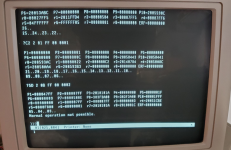
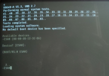
During startup, I get a few error messages, followed by "normal operation not possible".

The CPU is a "new one" recently bought from Ebay.

Apart from the CPU, two DSSI Drives (RF71 & RF73) are installed in the system and 2x 16MB Boards.
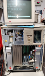
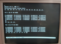
1711964536516.png

1711964572848.png

1711964591020.png

The errors are present with and without DSSI connected, with and without terminated DSSI connector at the enclosure (see picture above).
The presence of additional memory will not change the error msg. "SHOW MEMORY" does not indicate faulty pages.

The KA640 will not boot from DSSI and will not recognize the drives.
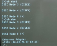
1711965085241.png

@Schroeder pointed me to https://www.pdp-11.nl/vaxsystems/mVAX3300/mVAX3300-info.html where a similar error message is reported.

Maybe this is no fault at all but indication of a false configuration?

The same enclosure but with KA650 & KFQSA & DELQA is working flawlessly including the DSSI subsystem.

I have another KA640 CPU which worked fine a few weeks ago:
1711965218963.png
including DSSI and network but it stopped working.
I get now no messages on the terminal at all and the LED indicator on the CPU panel is constantly showing an "F" - Initial State - no code executed.....
Eproms have been checked and ok...

Any ideas how I might move forward?

Thanks a lot
Stephan
 
I get now no messages on the terminal at all and the LED indicator on the CPU panel is constantly showing an "F" - Initial State - no code executed.....
Eproms have been checked and ok...
The CPU Board is on my table now. I did another visual inspection of the cleaned area of the board which was mainly impacted by a battery leakage. I soldered some parts even knowing that they had good contact just to be safe in case there is maybe a small cut which only disconnects when the board is inserted into the QBus. But with no success.

Obvious is the DC OK, green LED, remains dark. The reason for the board not starting. The signal DC OK is present on the QBus connector. Now, of course I need to understand what the board needs beside DC OK from QBus to function.
The board itself is no more complex than any of the boards from that area but schematics are difficult to find. My hope was on the VAX 3100 schematics but those are a really bad scan.

Does anyone has any schematics from a 3100 or QBus CPU card or an idea how these kind of boards deal with DC OK?
 
Check the power supply voltages. DC OK - off is a symptom that either +5v or +12v are out of tolerance. Electrolytic capacitor failures are common in equipment of this age. Processors won't attempt to start until this is corrected and DC OK is asserted.
 
The BA Box the CPU is sitting in is my test setup. Other CPU boards does work. Voltages are ok, DC OK and PO OK is present.
The Board did work before is was cleaned from acid. I have checked the cleaned area and traces are looking ok. Without schematics I will be lost ...
 
You should also check for bad solder joints, a microscope or magnifier (or magnifying camera) might be necessary. It may be possible when you cleaned it a bad joint opened up.
 
Does maybe anybody has such a CPU in user and can state if the "error messages" from the first posting point to a configuration error or an hardware issue?
 
Maybe a little late. I don't know if the KA640 is smart enough to do this, but most of the later boards respond to "T 9E" with a list of diagnostics. That list does not correspond to the countdown shown on the console. If your system doesn't do anything useful in response to "T 9E", just try something like "T 0" and hopefully it will reply with something like "Unknown test - use T ## for a list of valid tests". The technical manuals tell you to go look in the boot ROM listings (which as far as I know were never available outside of DEC), which isn't very useful. Anyway, match up your 57, C2 and 5D errors with the diagnostic list to see what's failing.

Once you know what's failing, you'll have a better idea of where to look. These boards have an annoying habit of wanting to test other hardware in Q-bus slots - a broken KZQSA also causes "Normal operation not possible" (which isn't actually true).

You always want the proper number of DSSI terminators installed. Normally one for the first internal bus and two for the 2nd, 3rd, and 4th buses (which your CPU doesn't have). There have been reports of the terminator power fuse blowing when no terminator is installed. These are usually little green guys that otherwise look like 1/4 W resistors. Some CPUs have them on the board, others have them on the back side of the CPU/memory faceplate (like the H3604 on a VAX 4000 Model 500).

BTW, looking at your first picture, you only seem to have one power supply connected to AC power. Those are not redundant - you need to have both plugged in.

Your DSSI controller is reporting itself as Node 6, which would usually indicate that this system started out as a DSSI cluster member (7 is the default). You're also missing a unit ID plug on the DSSI OCP (which may be normal if you only have 2 drives in there). But check and see how many drives you have. Unless you do some magic with PARAMS on the DSSI drive itself, a missing / incomplete OCP can cause all sorts of troublesome malfunctions.

Once you get things sorted out, I suggest seeing which disk (if either) has bootable VMS media on it. Boot from it, and run DSSI tasks VERIFY and DRVEXR on the other drive (you can't run them on the booted system disk). The RF73 has a MANDATORY firmware upgrade to T392F. It's so important it's been in sys$etc: on VMS disks since it was released, adn to this day you can find it on VSI Alpha 8.4-2L1.
 
Back
Top