• Please review our updated Terms and Rules here

Kaypro II

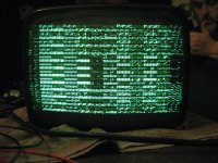
I've connected everything back up and tried to get some better pictures:
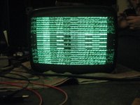
IMG_6382.jpg

IMG_6384.jpg


Having run it in the dark there was no sign of any flashes or arcing on the back of the tube, or the video board.

Sorry the pictures arent very good - I hope it does show though that the stuff is largely formed from proper characters not just random dots etc.
 
Is the problem likely to be the video board here or is it more likely to be the video section of the logic board?

If we think the video board is ok Im thinking it would be a good idea to put the boards etc back into the case on the basis that the logic board is easily accessible when it is generally back together.

I've sourced replacements for all the screws in this machine - mostly stainless. I find quite often the heads of screws are quite rusty I guess where screwdrivers have damaged the galvanistion on the screws. They should arrive tomorrow.
 
Of the two Tandon TM100 floppy drives, is the A: drive the one with resistor shunt thinggy or the other one please?

I know I should have written this down - could have sworn I did but can't find it.
 
I just popped the top on my Kaypro II to double check this. Drive A is on the middle of the cable. Drive B is at the end of the cable AND has the terminating resistor.

~Mark
 
Of the two Tandon TM100 floppy drives, is the A: drive the one with resistor shunt thinggy or the other one please?

I know I should have written this down - could have sworn I did but can't find it.
Maniak's probably right,but FYI the terminating resistor has nothing to do with Drive A or B; although it's not critical it should go on whichever drive is at the end of the cable.

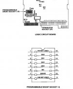
Drive A or B are determined by a DS jumper; on the TM100 it's usually a DIP jumper plug with one or more links cut:

TM100Jumpers.JPG
 
These drives weren't connected when any of the tests (other than the individual drive tests were done) but today I noticed something:

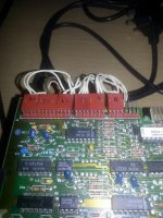
IMG_20120630_124137.jpg

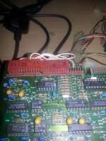
IMG_20120630_124144.jpg

The first image is th Drive B, and the second is of Drive A.

On the first image you can clearly see where the capacitor that we think was shorting the whole system, and blew when the drive was tested.

On the second image there is something very very odd about the way in which the connectors 8, 9 and 10 have been connected.

These have never been disconnected and were like it when the machine came to me.

I assume this is wrong and needs correcting.

Does this throw any light on what the problem with the logic board is? i.e. would this have blown a specific chip on the logic board?
 
Good catch! Drive A is almost certainly connected incorrectly, there should be gaps between 8 & 9 and 10 & 11 as per drive B.

Those are the LED, the index sensor and the WP switch; possible but unlikely that it damaged the drive, but extremely unlikely that it would have damaged the system board.

Looks like someone's been poking around before you; that always makes troubleshooting more, umm, interesting...
 
Right, I've returned all the parts except the two floppy drives to the original case for their own protection, and for ease of working on the logic board.

Ive tried wriggling all the chips a bit, and pressing down on them, but when the machine is powered on, all it does is the same displays as above.

I guess now I have to begin reseating? Any tips where to start?

Ive printed the schematic for the logic board. Its three pages: CRT control, CPU and memory, and IO/Disk controller, but I can't really decide which area of the board to start.

On the floppy drive front btw, I've replaced the blown capacitor, and put a bit of silicon grease on the rails carrying the heads ready for their return to the machine. I've also corrected those connectors on the one drive as well. I've left the drives out at the moment mainly to simplfy what is in the machine slightly, but I could pop em back in if you think it would be better.
 
Given that you have an out-of-sync display with random garbage on it and you didn't mention the floppies being accessed, I'd start with the CPU section first.

Do you own a logic probe or oscilloscope so that you're able to see pulsing signals?
 
I have a dual channel oscilloscope. I'm fairly new to using it but I've been reading up and watching lots of youtube vids on how to use them.

What do you need me to do?

Do you want me to install and connect the floppies so we can see if they are accessed?
 
Definitely something wrong in the video section; those dots and lines on either side of the main display should be a big clue but I'm just heading out for a few days' holiday.

Save me looking for it: where are the schematics for your particular board to be found?
 
Given that you have an out-of-sync display with random garbage on it and you didn't mention the floppies being accessed, I'd start with the CPU section first.
Always hard to tell from a camera shot, but it doesn't really look out of sync, nor is it completely random; those artifacts on either side look like they should tell us something though.
 
It looks like some parts of the display are pretty constant?

What you could try is swap some of the chips on P 6.3 with one of the other chips of the same type; if they're both OK then nothing should change, but if one has a problem then it should create different symptoms when it's in a different location.
 
Could be something as simple as a bad ROM at this point if the display's not rolling (it's hard to tell, what with a video of a CRT display).
 
As you say it is hard to tell, but I've just been looking at it with Dad.

We think it is rolling but not in (Ugghhh this is hard to express) a image is unstable on the screen type way, but almost as if the text on the screen is cycling down a row every time it blinks, at least in some areas of the screen.

I may have just found a major problem though - which isn't going to help at all.

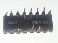
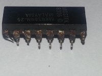
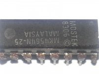
In one of my earlier postings I commented that in one row of chips all the chips have corroded pins where none of the other chips around them have any pin corrosion at all. I just decided to very very carefully remove one of those chips:

IMG_20120701_155532.jpgIMG_20120701_155559.jpgIMG_20120701_155644.jpg

Other than the eight RAM chips, and very very slight corrosion on a few pins on the two Z80 PIO chips, all the other chips are perfect.

Why would the RAM chip legs corrode like this?

Where can I buy replacement chips?
 
Just about any 64Kx1 (e.g. 4164) DRAM will work here--the Mostek's aren't special. On eBay.co.uk, there are several sellers of KM4164 chips for not much money.
 
Back
Top