• Please review our updated Terms and Rules here

KIM-1power up questions

lagomorph

New Member
Joined
May 15, 2022
Messages
7
Location
Virginia, US
I recently received a Rev. F KIM-1 that appears to be in excellent condition. Any suggestions as to any precautions to take before powering it up? One of the electrolytic capacitors, C1 shows a resistance of a few hundred ohms which doesn't seem great. I have a current limited supply. Any danger of damaging anything (other than perhaps the cap) by applying power? I could replace the two electrolytics but I'd like to avoid soldering on it at all if it's at all possible.
 
Electros have a limited life span and are generally the most unreliable part of any electronic equipment. If they need replacing then replace them.
Tantalums tend to go short circuit after several years so you might to check on them, if there's any there.
 
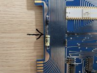
Generally, electros tend to dry out and lose capacitance and their ESR rises as they age. They can short out on more rare occasions, but as noted it is the TANT capacitor that has the penchant for shorting out.

Likely the electrolytics on this sort of board will be at least ok for test purposes.

It is more of a worry say if your power supply is original or not and has been disconnected in the past or has had its wiring tampered with.

Generally there are two severe mistakes you can make powering up your pcb that could be devastating and destroy multiple IC's, these are:

1) incorrect polarity (+ &- connections reversed)
2) Over-voltage applied.

They are the two things to avoid.

This risks occur when power from an external generic power supply is applied to a pcb's power terminals (it unlikely happens when there are polarized connectors from a previously working supply).

So be careful.

If you are really paranoid about these sorts of accidents, like I am, there are some things you could do to mitigate these possible errors:

For the reverse polarity risk you could pre-wire a power diode , like a 1N5404 across the power supply input terminals on the board , with the diode cathode (the line) connected to the + terminal. And have a 1A or similar fuse in series with the power supply output/s. This way if you connect it in reverse, the reverse voltage across the PCB is limited to around 0.8V and the fuse blows.

For over-voltage you can also use the fuse & fit a TVS (which is like a power zener diode) to the +5V supply which clamps the voltage to about 6.5V. These also conduct in reverse too. A suitable part for a 5V supply is the 1N6267A(1.5KE6.8A), obviously you need a different one to protect a 12V supply rail such as the 1N6275A:


Otherwise if you have a supply that is variable, (or an analog supply you can power via a Variac) it makes sense to bring the voltage up slowly measuring the current, in case something is drawing too much current. Without fusing if there is a shorted part (like a TANT cap if there is one) it can fuse a section of the pcb, which is a shame, if it could have been avoided. (don't use a variac on a modern SMPS)
 
Last edited:
That capacitor is bad. Even it if is not swollen, you should change it with a new one.

But that remark, about is measuring a few hundred Ohms, didn't say whether it was measured in or out of circuit, if it was isolated out of circuit, clearly the capacitor is bad.
 
Thanks for all the replies. I measured the cap in circuit so I'm not absolutely sure. Both electrolytics, C1 and C4 have a little bit of corrosion on the negative side. I don't think there are any tants. I don't believe C18 is and the rest are large and yellow (polyester?) My 5V power supply is based on a DROK adjustable buck converter and I can limit the current to 1.2A (or lower). I'm not connecting 12V yet. I'm leaning toward replacing the electrolytics once I get some axial ones.
 

Attachments

  • C1.jpg
    C1.jpg
    941 KB · Views: 19
  • C18.jpg
    C18.jpg
    937 KB · Views: 19
The resistance measurement has no meaning with the Cap in circuit. You could always test its ESR in circuit, but I don't think it is required.

That electrolytic cap is most likely fine. The "corrosion" you see is not leaked electrolyte, it is due to the lead weld on the negative side of the capacitor and it is normal.

It is almost 100% certain the brown (dipped silver mica cap) and the yellow film caps are fine.

I would just leave it as it is considering the historical significance of the board and not replace or un-solder anything unless you have good scientific evidence it is defective.

I think it is ok to power it , but as I mentioned, be very careful about voltage and polarity issues if it is the first time this power supply has been connected and double check the supply outputs with the meter for correct voltage and polarity before you apply them to the board.
Good to know, thanks. I'll be super careful powering it up.
 
Let us know how it goes. Mine had been powered up backwards and blown one of the ROMs as well as the CPU.
If that hasn't been done, the most common problem is bad RAMs.
I've made a diagnostic board to test the KIM-1. If you have problems I may be able to help.
Dwight
 
It's working! Everything I tried so far looks good including stop and single step (after remembering to set the vectors). It's drawing about 0.7A. More testing needed!
 

Attachments

  • kim-1-timer.jpg
    kim-1-timer.jpg
    1,016.3 KB · Views: 15
But that remark, about is measuring a few hundred Ohms, didn't say whether it was measured in or out of circuit, if it was isolated out of circuit, clearly the capacitor is bad.
Hugo, I would think in-circuit the resistance would read lower than out of circuit. But also I was thinking he used a proper ESR meter. I'm glad there was no puff of smoke in his classic KIM.
 
Good that it is working and you clearly powered it up correctly. The white ceramic IC's on that board look very nice.

Now that you know its operating current at 700 mA you could put an 800 mA or 1A fuse in series with the supply to it, as an added precaution. bare boards have a habit of things either getting under them (tools or other conductive objects) or things falling on them and shorts occurring.
 
Let us know how it goes. Mine had been powered up backwards and blown one of the ROMs as well as the CPU.
If that hasn't been done, the most common problem is bad RAMs.
I've made a diagnostic board to test the KIM-1. If you have problems I may be able to help.
Dwight

What an awful story. These sorts of mistakes are all too common.

One classic was with the HERO Jr. Robot. They made it to be run from two 6V gel batteries in series for a 12V supply. Guess the two things that went wrong ? People fitted the cells in reverse destroying most of the IC's. But when they were not doing that, they accidentally fitted two 12V gel batteries by mistake and over-voltaged it.

Most of the chips could easily be replaced, except for the amazing Votrax SC-01 speech synthesizer IC (which are now nearly unobtainium) .

To prevent this disaster in my HERO Jr robots I fitted a power zener to clamp over voltage and reverse polarity, the story about this is here:


Oddly, Heathkit never made a service manual or schematic for the radio board so I reverse engineered and documented it. The IC's in the Tx and Rx circuit are also very rare now and had their origins in home automation systems like remote controlled garage doors.
 
A fuse sounds like a great idea. I have a current limit set on the supply of 1.2A because that's the spec for the KIM-1. I'll probably lower that to 1A but I still have to trust that the electronics in the supply won't fail somehow. I have a voltage limit set to 5.1V in the supply as well. There is a 6.2V zener on the board between 5V and ground. Perhaps that would help a little in the case of over voltage.
 
A fuse sounds like a great idea. I have a current limit set on the supply of 1.2A because that's the spec for the KIM-1. I'll probably lower that to 1A but I still have to trust that the electronics in the supply won't fail somehow. I have a voltage limit set to 5.1V in the supply as well. There is a 6.2V zener on the board between 5V and ground. Perhaps that would help a little in the case of over voltage.
If you used this part I mentioned, in conjunction with the fuse, it would save it:
1N6267A(1.5KE6.8A)
 
What an awful story. These sorts of mistakes are all too common.

One classic was with the HERO Jr. Robot. They made it to be run from two 6V gel batteries in series for a 12V supply. Guess the two things that went wrong ? People fitted the cells in reverse destroying most of the IC's. But when they were not doing that, they accidentally fitted two 12V gel batteries by mistake and over-voltaged it.

Most of the chips could easily be replaced, except for the amazing Votrax SC-01 speech synthesizer IC (which are now nearly unobtainium) .

To prevent this disaster in my HERO Jr robots I fitted a power zener to clamp over voltage and reverse polarity, the story about this is here:


Oddly, Heathkit never made a service manual or schematic for the radio board so I reverse engineered and documented it. The IC's in the Tx and Rx circuit are also very rare now and had their origins in home automation systems like remote controlled garage doors.
You can see the final version of the ROM replacement on:
#38
It was composed of two small boards that hide under the 6532. One board was dedicated the messy pin swapping difference between the 6520 and the 6532. The other had the PAL that did the address decoding, that was jumper selectable for either the 002 or 003 ROM, as well a small EEPROM that held the ROM code. Rather than preprogram the EEPROM, it was programmed on the KIM with the desired ROM code from the DEBUG board.
The schematic for the debug board is on an earlier page and one of the other members has the code for it on his web page. The debug board is quite useful even if the ROM chips are undamaged. It has a series of test to check out every thing from the CPU, RAM, ROMs, keyboard and display. I did not include code to test the cassette interface as the documents for the KIM should be enough.

Dwight
 
Back
Top