cj7hawk
Veteran Member
Hi All,
I know this is a bit of a weird request, but does anyone happen to have an oscilloscope and a functioning Matrox ALT512 with 4 intensities in 256x192 mode and is able to tell me what the signal levels are?
The manual itself is excellent and contains all the timing and voltage information, except this one detail...
I've rebuilt my video circuit desing around a similar output to the Matroz and am trying to work out how deep the intensity differences were and the voltages are a long way from where I expected them to be when they looked right on the screen ( Black, Dark Grey, Light Grey, White )

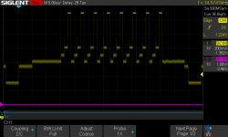
This is what I'm getting from my 2-chip raster circuit at the moment and while the syncs and black levels all look OK ( it's about 1v PP, 0.7 on the video from black to white, and I know the Matrix was 1.4v PP but I can adjust that ) originally I thought I'd have to have the levels all fairly evenly spread, and found to get 4 visible graduations of grey, I had to drop all the grey levels almost to the black level, otherwise it's very hard to distinguish the grey from the white. It also might be because I'm pushing the signal into a LCD panel at present.
The other thing that isn't certain from the ALT512 manual is whether or not the composite output includes the setup section ( blanking lower than black ) - This is something else I'm trying to find out.
If anyone knows how Matrox did it, or can take a snap next time they have their scope and S100 system out, it would be very much appreciated -
Thanks
David.
I know this is a bit of a weird request, but does anyone happen to have an oscilloscope and a functioning Matrox ALT512 with 4 intensities in 256x192 mode and is able to tell me what the signal levels are?
The manual itself is excellent and contains all the timing and voltage information, except this one detail...
I've rebuilt my video circuit desing around a similar output to the Matroz and am trying to work out how deep the intensity differences were and the voltages are a long way from where I expected them to be when they looked right on the screen ( Black, Dark Grey, Light Grey, White )

This is what I'm getting from my 2-chip raster circuit at the moment and while the syncs and black levels all look OK ( it's about 1v PP, 0.7 on the video from black to white, and I know the Matrix was 1.4v PP but I can adjust that ) originally I thought I'd have to have the levels all fairly evenly spread, and found to get 4 visible graduations of grey, I had to drop all the grey levels almost to the black level, otherwise it's very hard to distinguish the grey from the white. It also might be because I'm pushing the signal into a LCD panel at present.
The other thing that isn't certain from the ALT512 manual is whether or not the composite output includes the setup section ( blanking lower than black ) - This is something else I'm trying to find out.
If anyone knows how Matrox did it, or can take a snap next time they have their scope and S100 system out, it would be very much appreciated -
Thanks
David.
