• Please review our updated Terms and Rules here

M847 extended edition > Bootloader in PDP style !

Follow up on Roland's "Extended M847" -

The board had a rough trip here – it got from the Netherlands to Chicago in two days but then spent more than two weeks languishing in the USPS ISC (International “Service” Center) before being sent on to me (I live less than an hour from the ISC). No indication of why it was held up – it wasn’t opened or inspected. Regardless, it arrived here in perfect condition but only just before the Thanksgiving (US) holiday weekend, so even then it was put aside for a bit.

I finally got to it last night and was very pleased to find that it performs exactly as described in Roland’s YouTube demo. At first, I was a little concerned about keying in all the selection codes but it actually works quite easily. After loading a few tests using the SW lever from the front panel, I switched to the Select button on the actual board and found it very easy to use. The “human engineering” is done quite well – the board gives just the right amount of time to enter the select codes, with a brief pause after startup and then it generates a halt and reloads the next test if selected. It also puts out a quick front panel “scanner” pattern on power up to let you know it’s there and thus provides a quick confidence test.

The board I received had the version 1. 0 code uploaded to the Atmega328. I tried to upgrade it to v 1.1 in place, using the BC01V connector on the board but I was unsuccessful – the Arduino IDE recognized the board but the upload failed with a security error. I’ll wait for more info from Roland on this; in the short term, I just removed the chip and installed it in an Arduino, reprogrammed it and then reinstalled it on the board. Not a big deal.

Really a nice job and a helpful addition to my PDP8 toolkit – thanks Roland!
 
Hi Jack,

Thanks for the review!

Good to hear the board arrived and works in you machine! For uploading the program trough
the BC01V you need to power up the PDP8. RS232 can't power the board.

If someone builds a new board with a complete blank chip, you need to take the
PCB out of the PDP and connect a Arduino Uno as ISP and connect the board like this:
https://raw.githubusercontent.com/R...sion-V1.1/master/Flash Arduino bootloader.jpg
In this way you can flash the Arduino bootloader and the Arduino uno is powering the M847 then.
(So it's easier to buy a pre programmed chip from ebay and skip this part...)

When the Arduino bootloader is already in the board you can upload the M847 firmware
trough the Arduino IDE with the BC01V of DB9 cable. The board then needs to be
in de PDP8 and you have to power-up the PDP.

These are the test programs 20 and above. (35 and 36 still need to be put in the software)
https://github.com/Roland-Huisman/M847-extended-version-V1.1/blob/master/Toggle in tests.pdf
You need this info to use those tests.

Does anyone know who wrote these tests? I want to put in the credits to the writer.

Regards, Roland
 
Last edited:
Just got my PCB fabs back today from JLPCB, built from Roland's v1.1 gerbers. ENIG finish with red soldermask, gold fingers with 45deg finish mill.

pcb.jpg

I had 10 pcs built, I'm only going to need a couple or three at most, so the rest are available. $10 each incl basic shipping to US addresses. More for special shipping. PM me if interested.

Don
 
Just got my PCB fabs back today from JLPCB, built from Roland's v1.1 gerbers. ENIG finish with red soldermask, gold fingers with 45deg finish mill.

View attachment 49858

I had 10 pcs built, I'm only going to need a couple or three at most, so the rest are available. $10 each incl basic shipping to US addresses. More for special shipping. PM me if interested.

Don

Ok, all the 10 boards are spoken for. That was faster than I thought (less than 2hrs). Guess I should have bought a larger quantity.

FYI, going to JLPCB website, uploading .zip'ed gerber file, and choosing options was pretty easy. For users in Europe or Australia (where shipping from US is lots of $$) probably a better option to go to JLPCB and get boards fabbed (in blocks of 10) and shipped to you directly, and then sell some to your local buddies ...

Don
 
Don,

When you say "gold fingers", does that mean hard gold on the fingers as opposed to the ENIG finish on the rest of the board? Seems like a great price, especially if that is the case.
 
I have a couple of boards going through JLPCB at the moment and asked exactly the same question.

No, the gold on the fingers is not hard gold.

I decided in the end to go with them despite this - the cost was prohibitively high for a hard gold finish from other suppliers.

Dave
 
I have a couple of boards going through JLPCB at the moment and asked exactly the same question.

No, the gold on the fingers is not hard gold.

I decided in the end to go with them despite this - the cost was prohibitively high for a hard gold finish from other suppliers.

Dave

Dave is correct; the board is all ENIG plated (~5u Au over ~200u Ni) as opposed to hard gold (30u Au over 100u Ni) on the fingers.

So the boards are not going to survive lots of insertion/removal events without some damage to the fingers.

But as Dave indicated hard gold is a high cost option (if it is even available, not all vendors will do it) these days.

But for the US$5.55 cost per board (incl shipping from China to California) that is about all you can expect.
 
A little update for the component list which I will put in the Github files as well...
The advice is to buy the ATMEGA328P-PU (picopower version) and not the ATMEGA328-PU.

A little background: You can use both the ATMEGA328-PU and ATMEGA328P-PU in
the board when they have the Arduino bootloader in it already.

If you bought blank ATMEGA328-PU chips, you have to do a little trick to load that bootloader in the chip.
I have both model chips running and I was not aware of this difference because the non
pico power version had the bootloader in it already. So thanks to Matthew Greer for mentioning this!

But to be honest, I would buy the pre loaded ATMEGA328P-PU version anyway...

Regards, Roland
 
Funny, I helped a member at our local makerspace programming his atmega 328 boards (audio synthesizer modules) yesterday, and we hit the same obstacle. I solved it in a different way, googled how to write the bootloader via the command line, and then just adding '-F' to the avrdude command line.
This article was the one we used as a reference.
And I never thought about looking deeper into that signature difference.
 
Last edited:
M847 Extended Edition - Notes on Building

M847 Extended Edition - Notes on Building

This note presents my experience in building Roland Huisman’s M847 extended edition Bootloader. My intent is to encourage others interested in the board but maybe hesitant based on skill level to take on building the board. I note that the forum topic has more than 5000 views, so I suspect there are more folks like me, who may not be “expert” builders, but would be interested in having the board if it is not too daunting to build and set up… it is a very doable project…
The board has been great to have installed in my PDP8/E. It allows painless loading of commonly used bootloaders, test programs and setups such as Kyle Owen’s SerialDisk program.

There are lots of ways to build the project, and I certainly don’t represent that the way I have gone about it is the best – I’m sure others have better ways..
Important credit goes to Roland Huisman for designing this great add for PDP8 folks. His contribution includes designing the board, writing the Arduino code and clearly and completely presenting the needed info for users (refer to his github site at https://github.com/Roland-Huisman/M847-extended-version-V1.1).

Sourcing of Materials
I followed Roland’s write-up and ordered the PCB online from JLCPCB.com and used the gerber files on his Github site. Ordering went very smoothly and I got the boards in about 10 days. I did make the mistake of ordering the stencil file. JLCPB got back to me via email the day after I placed the order and helped me understand that I did not need it. Cost for 5 boards was $46, including shipping. (if three folks are being held up by this step, I can send you one of my left over boards… contact me).

I purchased the individual components from Digikey using Roland’s Bill of Materials in xls format. Use his latest version, as there are a couple of minor updates. I copied the DigiKey part number and quantity columns into a separate spreadsheet and oploaded that directly into the DigiKey order site. I then adjusted for items that I did not need from DigiKey or where I wanted a spare or two. Worked great..

I ordered the Atmega328-PU from the internet, with bootloader installed – thinking that would save a step that I was not familiar with. Long story short, I found that my Arduino Uno does not have native support for the 328-PU. The Uno wants to see a 328P-PU, so I could not download Roland’s code onto the board, nor upload the Arduino bootloader. I know there are ways to get around this, but I recommend (consistent with Roland’s forum post) to purchase the Atmega328P-PU. Digikey has this, and it is included in Roland’s most recent BOM. As I was working to figure the above out, Roland suggested a work-around that got my board running – use an Arduino Uno board that has a working 328P and load Roland’s code on to the board then move the Atmega328P chip to the bootloader board. That worked well as I waited for the Atmega328P-PU. With arrival of the Atmega328P-PU, I was able to install it on the bootloader board, burn the Arduino bootloader using Roland’s instructions and a 6-pin IDC cable with his mod (sourced from Adafruit part number 371 at $2.00). I used the Arduino Uno to then download Roland’s code onto the board from my PC’s com1 port using a DEC BC01V serial cable from one of my M8655 boards.

Assembly Notes
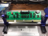
Placement and soldering of the components went well, using the BOM and the pdf file showing placement. An assembly aid that new builders may fine useful is an adjustable circuit board holder (I use an Aven 17010, $12.20 from Amazon with a makeshift extended-length center channel):

A couple of other tools that new builders may find helpful in assembly – a lead bending/forming tool (Jameco 106884 at $4.95) and an IC pin straightener (Jameco 99363 at $7.95):

Operation
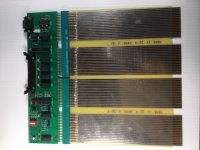
Once assembled and with the right Atmega328P-PU installed and loaded. I installed the board in my PDP8/E, using an extender board to help with initial testing and familiarization. I use a DEC Compatible Board Extender with 72-125C-EL connectors from Douglas Electronics (part number 6-DE-8-C) for $60.

On startup of the PDP, Roland’s bootloader board has the AC register show a scan of lights back and forth, then either loads the pre-set program on the board’s DIP switch or awaits either SW keypressing or the small button on the board to load one of the pre-programmed programs.
I know I speak for many others in saying thanks again to Roland for developing and making this board so readily approachable to the PDP8 community.
I also know that this write-up is a little sophomoric and unneeded for many of the experienced PDP8 community, but it may help some folks that are on the fence in taking this on to feel more confident that it is readily doable.

PCB Holder.JPGPDP Omnibus Quad Extender.JPG
 
...
I ordered the Atmega328-PU from the internet, with bootloader installed – thinking that would save a step that I was not familiar with. Long story short, I found that my Arduino Uno does not have native support for the 328-PU. The Uno wants to see a 328P-PU, so I could not download Roland’s code onto the board, nor upload the Arduino bootloader. I know there are ways to get around this, but I recommend (consistent with Roland’s forum post) to purchase the Atmega328P-PU. Digikey has this, and it is included in Roland’s most recent BOM. As I was working to figure the above out, Roland suggested a work-around that got my board running – use an Arduino Uno board that has a working 328P and load Roland’s code on to the board then move the Atmega328P chip to the bootloader board. That worked well as I waited for the Atmega328P-PU. With arrival of the Atmega328P-PU, I was able to install it on the bootloader board, burn the Arduino bootloader using Roland’s instructions and a 6-pin IDC cable with his mod (sourced from Adafruit part number 371 at $2.00). I used the Arduino Uno to then download Roland’s code onto the board from my PC’s com1 port using a DEC BC01V serial cable from one of my M8655 boards.
...

This behavior is not my experience. It IS true that putting a blank 328 on an Arduino board will not allow the Arduino tools to download the bootloader, as the tools check the silicon device ID, and it is different between the 328 and 328P. There is a way to fool the Arduino (really avrdude) tool to work around this (using the -F switch to force programming and ignore device ID) but it takes a bit of hacking to do it.

Once programmed with the bootloader (and correct fuses) the 328 behaves exactly the same as the 328P. The programming model is identical, and Arduino software does not care. So the statement: The Uno wants to see a 328P-PU, so I could not download Roland’s code onto the board, nor upload the Arduino bootloader. is not quite accurate, at least in the first half. The second half re: the bootloader is true, as I indicated previously. But once the bootloader is correctly programmed, Arduino IDE can download software to the 328/328P identically. I have several Arduino 328P boards with DIP devices and I have used both 328 and 328P devices in the same socket, and downloaded Arduino sketches, no problem.

Other than that nit, it is a very good writeup on building the board and sourcing all the requisite parts.

If you do insert the board directly into the backplane, I would exercise caution around the DB9 socket as it might inadvertently short against an adjacent board in a slot. I would recommend using some insulating kapton tape over the exposed topside metal edges of the DB9 connector, or gluing some insulating ~1/2" standoffs near the connector to keep it spaced away from the next slot board.

Don
 
Well..... another boot loader is in service on a PDP8E. I had followed this thread since the beginning, but was unsure of how to exactly have a board made. I'm studying Ki Cad, but am not to the point where I can do what is needed. Then when Matt G said he had some extra boards, I popped off a message. After the boards were in hand, I purchased the parts to populate the board. I took Roland and Matt's advise and purchased a Arduino with the boot software installed. I purchased two chips for $10 with shipping om eBay. Installing the parts were relatively easy. Next was where I stumbled a little. I didn't know anything about Arduino. I saw Roland's *.ino file, but how does one install it? After a few messages with Roland, watching a bunch of you tube films and reading about Arduino. I found all that is needed is to download the Arduino IDE. The next problem is that my modern computer has a com port, but it is not brought out to a DB9 plug. So I had to purchase a cord for that and a null DB9 cable. Now, I figured I was set to try installing the program. I downloaded Roland's *.ino file from GitHub to my computer. Started up the Arduino IDE and found the ino file and opened it. Next the boot loader board was powered up and connected to my computer via the null cable. From the Arduino IDE program, I clicked the verify button and the upload button. All that took place was a message was displayed at the bottom of the screen that 8202 bytes were transferred. Well, no bad stuff was written so I figured why not try the board. This required going to the cold basement. After bundling up I plugged the board into the PDP8E and the front panel light did the back and for worth pattern and I was optimist that it would work. The PDP8E switch was toggled and the first program (Serial disk Boot) was loaded and OS/8 started up. Hot Dog! I also had taken the time to load up my XRIM.RIM for my REMEX paper tape reader into Roland's program. So, I dialed it up and the REMEX ran as it should. The XLBAA.bin was loaded and after that I could load a MAINDEC file which also worked fine. My XRIM file was added via the IDE program. Programs 16 and 17 were commented out. So I relabeled programs 2-15 as 3-16 and inserted my REMEX boot loader XRIM as program 2
Code:
  const PROGMEM word Program_02[] = {0x0200, 0x0000, 0x4220, 0x7106, 0x7006, 0x7510, 0x5200, 0x7006, 0x7040, 0x3232, 0x4220, 0x7040, 0x0232, 0x7040, 0x7420, 0x3633, 0x3233, 0x5200, 0x0000, 0x7240, 0x6506, 0x6502, 0x5223, 0x7240, 0x6503, 0x6505, 0x6504, 0x5620, 0x0200}; // REMEX reader load
Where 0x0200 is the beginning of the program, 0x0000 is the extended address. The last 0x0200 is the XRIM starting address and the bytes in between are the XRIM code.
Before my fingers and feet got cold, I also tried program 32, the terminal test and this also worked. I want to try some of the other programs, but will wait until I feel better and it warms a little. This project will enhance my PDP8E immensely. And now that I know a little about the Arduino, I think I may purchase a UNO and experiment with it. Thanks a million Roland, you to Matt for the boards. Mike
 
@Mike, very nice to hear your success story! Well done :D

For others, I still have this prototype board which I used in the first demo on YouTube.
Prototype.jpg

It's not as fancy as the newest one because there is no RS232 but only a TTL level
interface to program the ATMEGA328. So if one has an USB - RS232 TTL converter then you
can program it as well. Or use an Arduino Uno to program the atmega328 and pull the chip.
This board is 100% compatible with the current software.

I've pulled the chips and crystal for the proto's of the current model but it is quite easy
to make the board complete and working again. In fact, it was already working :D

So if anyone likes to have this board just reply here. It's for free, just shipping costs. :xmas:

Regards, Roland

BTW, does anyone know how I can add the Github link to my first post? I can't edit it anymore...
 
...

Regards, Roland

BTW, does anyone know how I can add the Github link to my first post? I can't edit it anymore...

Editing a post is now disabled about 15 minutes after you posted it. So you have a very small time window to change/correct/update your posts.

An alternative would be to create a blog entry. This is like a post, but stands alone, and can be edited by the author any time (even years later).

Start here: http://www.vcfed.org/forum/blog.php

Blogs are a little bit harder to find, you have to search for them, but they are more flexible and you can link to them from posts.

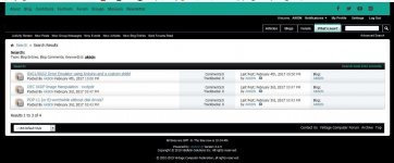
For example, I have these under my userid: Capture.jpg

Don
 
Hi Don, thanks! 15 minutes is quite short to edit.
As an alternative I've added my GitHub link to my signature.

And I wonder who is going to get that prototype... :dontgeti:

Regards, Roland
 
Yet again, my reply seems to have been deleted.

I would be interested if still available.

I left my email address last time; maybe my reply was censored as a result.

I will try to send a personal message

Steve G7PSZ
 
Currently I'm working on a firmware update for the M847 Extended edition.
I will add the kaleidoscope like Vince did and the RX01 address is updated.
Some other minor updates will come as well...

The intention of the BIN LOADER is that you can start the bin loader and load BIN files directly.
But a few times I've seen some strange behaviour according the BIN LOADER program.
Has anyone used this already? Any experience?

Can anyone point me to the original BIN LOADER listing with the octal values?
It seems I haven't used the original from DEC and it seems that it doesn't always work properly.

And if there are any other suggestions please don't hesitate, just ask...

Thanks in advance!
Roland
 
Back
Top