• Please review our updated Terms and Rules here

Mac SE Checkerboard pattern after cleaning battery leak

kitor

Member
Joined
Oct 1, 2017
Messages
36
Location
Poland
Hi,
Just bought Macintosh Plus and Macintosh SE 1/40 on local market. Plus works (but I need a keyboard ;) ), SE was known to be broken / showing only horizontal dotted line (not solid).
After disassembly I saw this mess:
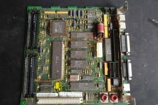
35077592_957964507696484_7880482221780369408_n.jpg

After touching battery it got even worse it was still half-full of it's content. I washed the board using IPA and toothbrush, then under shower, under IPA again and got it almost clean.
Weird is that no traces got corroded, only some pass-throughs near battery that I was able to fix quickly.

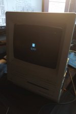
Now it boots to this checkerboard-like pattern. Pattern itself depends on how many/what configuration of RAM sticks is installed. Board was configured to 2/4MB, sticks are unknown size - two "GB11000S-8/9" with 8x KM41C10000BJ-8 chips (google gives no results) and two Nec MC-157A with 2x Nec 424256-80 (so probably 512k/stick)
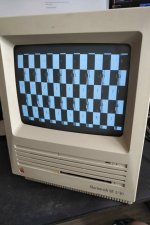
34849785_957929017700033_558562339385769984_n.jpg

Up to now I checked voltages on external floppy connector - both 5v and 12v are fine. Checked analog board for visible bad joints - all looks OK. Of course in case of this leak disaster, traditional troubleshooting won't help so I'm looking for any clues.
Unfortunately googling for checkerboard pattern gives only "bad capacitors" results, no technical explanation what this state shows or where to look. I have a 100MHz scope to poke around, just need any info where to start.
 
But he has an SE and not an SE/30.
While it uses more conventional axial caps which are still pretty old now I have found the SE logic boards are a lot more robust when it comes to the caps getting old. MY bet is battery damage somewhere.
 
You might have to suck some of those chips off the board, some of those chips may have battery goo under them that damaged traces. Be careful with the legs on those chips too because some of them look pretty eaten up.

You also might want to use something to neutralize the battery goo like vinegar because IPA isn't going to.
 
Unfortunately 'desolder everything' seems now a way to go. I noticed that many pass-through holes were corroded. I tried to 'refresh' soldering of chips where leak went using fresh tin and now I have a black screen :|

I got everything needed to create plug-in extension of analog-digital cable, fun fact is that ATX power connector fits in it in one position. Magic smoke-less PSU donor is waiting.

In worst-case scenario working boards are not that expensive, but I think it's better to at least try to repair every piece of such old hardware.
 
After desoldering, cleaning and resoldering main CPU, one of 74LS245n where corosion went, all passive elements on it's way (well, everything except Z8530H CPU - I wasn't able to desolder this one from board), problem persists.

What I noticed:
- Checkerboard pattern changes with 2/4 - 1M jumper and with different RAM configurations.
- I took RAM from working IIcx and got white screen instead of pattern
- In all cases there are those lines that I suspect are caused by problems somewhere between CPU and memory
- Lines changes between 'boots'
- Same happens with and without ROMs in place, so it's not even trying to boot.

I'll go with replacing all electrolytic capacitors now.

[e]
If I understand architecture correctly, RAM is connected directly to BBU and indirectly to CPU. Zilog is just a serial port controller so it shouldn't be a problem on this boot stage.

After re-soldering BBU socket as well as resistor arrays between BBU and RAM, now I get same "pattern" of lines each time.

More observations - there's output on 15,667200 oscillator, there's no clock on main CPU. According to Apple Guide to the Macintosh Family hardware, BBU generates clock for CPU.
I see clock on output of GLU chip (that buffers it for IWM, BBU and processor direct slot) master clock is coming to them indeed.

CPU clock line is low all the time.

I'm looking for any docs about BBU then.
 
Last edited:
I would go back to the analog board and re-inspect it. It could still have bad solder joints, try gently flexing it from one of the corners while its on and see if anything changes. Hairline cracks in solder joints can be very hard to see.

If you have corroded VIAs on the logic board, you may want to see if they pass a continuity test after you clean them up.
 
Flexing analog board changes nothing. Well, what would it change if there's no clock for M68000 at all = main CPU is not working?
As for vias - good point, i re soldered some but not all.

Right now I seem to have exactly the same "line" pattern over checkerboard on each boot. That's something new.

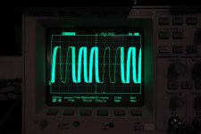
I poked with oscilloscope a bit more. Master clock is going where it should. However on clock input of serial controller (Z8530H) I see this:

35067646_958682527624682_722527259985969152_n.jpg

This should be around 3MHz clock generated by BBU. Looks (and measures) like 3MHz clock overlayed with some kind of high-frequency signal (100MHz oscilloscope reports from 3MHz up to 200MHz randomly as this "filling" signal shows and disappears)

As Z8530H was the first chip on corrosion path, I'm going to desolder it anyway and look for traces between it's clock and BBU clock output.

[e] A friend of mine suggested that this looks like cold solder joint somewhere.

I found partial board schematic on this site: https://museo.freaknet.org/gallery/apple/stuff/mac/andreas.kann/schemat.html
It's 1-bit GIF that's a bit hard to read, but quick 1,5px gaussian blur + sharpening fixes that. Unfortunately only half of schematics it there.
 
Last edited:
Flexing analog board changes nothing. Well, what would it change if there's no clock for M68000 at all = main CPU is not working?

Sketchy power connections can cause all sorts of weird problems. I saw where you measured power directly from the floppy port, but probably not while flexing the analog board. I'd poke the scope across the power rails if you haven't already to see if they're clean and not full of trash extraneous signals or high ripple.

This should be around 3MHz clock generated by BBU. Looks (and measures) like 3MHz clock overlayed with some kind of high-frequency signal (100MHz oscilloscope reports from 3MHz up to 200MHz randomly as this "filling" signal shows and disappears)

Might be a clock divider interfering with the scope.
 
I saw where you measured power directly from the floppy port, but probably not while flexing the analog board.

Actually I did that yesterday after it was mentioned for the first time, no changes were visible on multimeter - both 12 and 5v voltages were rock-solid.

Chips legs looks bad indeed, but they are not eaten up fortunately - parts that were going through board were clean, those exposed to leak cleaned nicely using sandpaper - at least on chips that I was able to desolder. In case of Z8530H it was still holding to the board, so I just applied new tint after sucking old - but will try to get it out again.
 
I don't see any layers indication but Macintosh Plus had 4 layers, so I would bet for similar design.
 
I cleared all vias in coroded area. Desoldered SCC and ADB chips (that are using this 3MHz clock), what's interesting - clock goes all the way to GLU chip. After removing resistor R23 near BBU (one side to clock source in BBU, other to mentioned chips) I measured clock from GLU - same effect.
Removed IWM too as it's socketed and shouldn't interfere at this point.

However (I'm still learning using oscilloscope features) when I paused measurements and scrolled through saved signal - the problem is that clock generated by GLU is just unstable as hell. Single pulse varies by almost 1MHz - that's what confuses scope in normal measurements.

I replaced most 33uF electrolytic capacitors, three are left original for now.

As main clock is stable and BBU is getting it for sure, I don't know where to look next.

Checked RAM slots using oscilloscope - I see all signals required by 256k sticks on each slot. Which is weird as it's supposed to have 1MB or 2/4MB and with 1MB settings, slot 1 and 2 are active, with 2/4MB all 4 slots are active.

and here I was going to post this but by accident found that I'm stupid -.-
I looked at CPU pinout the wrong way. Perfect clock is on CPU pin 15. Aghhh... So time to check connections between ROMs and CPU. HIGH rom was also on corrosion path.

[e]
And here it goes! It's partially alive!

What I found is that both RESET and HALT lines are driven LOW (active) and for some reason they are both short. On working computer I applied 5V to them... and got sad mac face!

35225375_959203087572626_5172260266523492352_n.jpg

Not sure about error meaning and where/why this short exists (according to schematics those should be separated). Half of chips is still not installed on board for sure.
Based on Mac Plus schematics I found pullup resistor (R13) for RESET line - 1k, it's ok. So something is driving this low.
 
Last edited:
Yes, however keeping in mind this short circuit between HALT and RESET + that I'm forcing it to HIGH as something keeps it LOW... that's not weird at all at this moment.

This short is not caused by BBU (exists with chip removed), nor CPU/under CPU (I cut the trace going to HALT from BBU - there was no short to HALT on CPU but lines were still shorted somewhere on the board.

Another observation - I can trigger this behavior only with two memory modules installed. When four are installed (independently from jumper configuration), this won't show. But indeed I never checked slot 3 and 4 for proper signals with scope.

And I think I have explanation for what checkerboard pattern is - just not refreshed RAM state displayed on screen. If I trigger sad mac face, turn off device and turn it on again without keeping RESET to HIGH - I get scrambled image (fading more each time ;) )

As for bus/memory - all connections between CPU and HIGH/LOW roms are ok, so at least D0-D15 and A1 - A15 seems OK. I used working RAM from Macintosh LC with same result. And there is some communication as sad mac face is coming from ROM (?, correct me if I'm wrong).
 
Last edited:
I was wrong about HALT/RESET short. They should be - they are literally connected on Processor Direct Slot both on schematics and on board (C12 and B12 pins). So for now something is keeping this low, or there's no reset from Sony UC.

And you won't believe this!

35294489_961484140677854_1304828901523980288_n.jpg

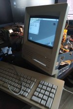
So I desoldered audio chip again, and tried resetting CPU by hand (this time on correct connector). And I got usual background!
After soldering ADB chip, got mouse and no system disk indicator, with disk connected it was hanging somewhere during MacOS boot - I added SCC back and it booted.

Sound UC is broken, at least RESET line part. It's LOW all the time. I isolated this single pin and after resetting CPU everything boots, and works, including sound.
I checked whole reset and power circuit, everything seems to be right. Schematics of this part is 1:1 from Mac Plus, just elements IDs are different.

So it's now up to a) finding working chip, b) designing own reset circuit.
BTW: Reboot from OS works as it doesn't trigger RESET line.

[e]
After a bit of research, there's a ton of ready to use reset circuits for cheap. So I'll go with option B.
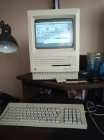
And photo of working Mac after installing clean OS 7.0.1. It has HD floppy with correct ROMs and IWM happens to be SWIM, so that was easy to pull off with PC and USB floppy.

mac.jpg
 
Last edited:
Well done - that's some decent troubleshooting. A lot of people would not have put the effort in and threw that board away.
 
That was a gamble - I found the cheapest (incl. shipping) board for the same price I bought a good desoldering station (ZD-915) that I needed for this, and will be useful for other projects ;)
Macintosh LC is already waiting with it's bad caps in PSU (no voltages - known issue with this model) and short in all directions on the board (I bet for capacitors again; RAM, HDD and FDD are working).

I decided that this board is probably repairable after I was able to clean this corrosion quite nicely. Had Commodore PC10-III in the past that board was so damaged I needed to drill a hole to get it off the computer case. Fortunately I had spare board and person interested in chips from damaged one in that case.
 
Last edited:
Hi,

I've got kind of similar issue, do you know how I could "reset the cpu by hand" ? Apply +5V on RESET pin ?

Thanks

Stéphane
 
Back
Top