• Please review our updated Terms and Rules here

Memodyne M80 fix up

falter

Veteran Member
Joined
Jan 22, 2011
Messages
6,580
Location
Vancouver, BC
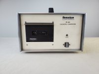
I bought this a long time ago and posted it here. Originally was thinking it was just a fancy digital cassette recorder, however subsequent Googlings proved it to be a ruggedized Z80 computer from the late 70s.

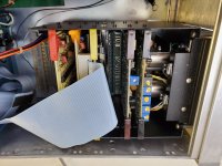
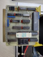
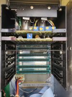
The interior is in excellent condition and it powers up without issue. However, despite supposedly working with a serial terminal, it does not seem to respond to any terminal connected to it. I've connected a breakout box and there are no signals at all coming out of either serial port, once of which is db25 male and the other db25 female. I've taken a guess that the male port, which is labelled J1, is the primary serial port. So far voltages check out okay. I haven't gotten to scope it yet it has a very small and tight card cage that is impossible to get the probes into. Need to create some kind of extender card.

According to documentation the machine can operate in a 'recording mode' or in a 'computer mode'. I am sort of suspecting that this machine may be waiting for a key sequence to kick over to computer mode. In the only documentation of any kind I've found describing operation, on a slightly different model with keys on the front, it says hitting Shift-FWD will enter computer mode. I'm thinking maybe there's a key sequence on a terminal that does the same?

I've dumped the EPROM and then I ran it through a disassembler.. I don't really understand what's going on there but I was wondering if anyone familiar with Z80 code might be able to pinpoint any input it's waiting for.

Many thanks!
 

Attachments

  • 20200607_203837.jpg
    20200607_203837.jpg
    1.4 MB · Views: 20
  • 20200607_203852.jpg
    20200607_203852.jpg
    1.7 MB · Views: 21
  • 20200607_204116.jpg
    20200607_204116.jpg
    1.5 MB · Views: 19
  • 20200607_204121.jpg
    20200607_204121.jpg
    1.6 MB · Views: 20
The file doesn't want to open for me.

Can you post the disassembly as a plain old .txt file please?

Dave
 
There are a couple of places where the code inputs from a port and sits and waits - but the occurrences I have found do 'timeout' after a while.

It looks like interrupts are used, so I wouldn't really expect 'polling' type of code to be present.

The disassembly has incorrectly disassembled some data areas as code. For example, some of the RAM is initialised from ROM.

Dave
 
Thanks Dave! From the documentation it sounds like there was an interactive console you could go into on some models... sort of like MIKBUG etc.. but since these things were used for specialized tasks I'm wondering if my EPROM was programmed differently and maybe doesn't allow you to do any sort of monitor-level stuff.
 
Unless you start to follow the disassembly (and comment it as you go) it will not be immediately clear from the disassembly what is really going on.

Dave
 
That's why I'm big on interactive disassembly. Look at the data, try to figure out what it is, then mark it up in whatever format it should be. It helps to have a tool that will keep track of which addresses are used.

Anyhow, a big problem I have with this is that if it really origins at 0000, then it's any missing sensible RST vector code.

There's also code at 005F which seems to be setting up an IM 2 interrupt vector table copied from 0300, but a lot of the entries in it don't make sense as vector addresses.
 

Attachments

  • MemodyneM80.bin.lst.txt
    24.9 KB · Views: 1
The file doesn't want to open for me.

Can you post the disassembly as a plain old .txt file please?

Dave
Here's the file as a .txt file dave - hopefully that works a bit better. I've never worked with assembly, but I did look at the dumped ROM file hoping to see some ASCII strings or such to indicate what it did or that it interacted with a user in some way. I don't see it though.
 

Attachments

  • m80eprom.txt
    36 KB · Views: 3
After initialisation, this is the 'idle loop':

Code:
0091 e7        rst     20h
0092 23        inc     hl
0093 f3        di     
0094 cb7e      bit     7,(hl)
0096 cbbe      res     7,(hl)
0098 2a001b    ld      hl,(1b00h)
009b c47106    call    nz,0671h
009e fb        ei     
009f 18f0      jr      0091h

rst 20h sets HL to 1B03h.

The code basically sits in this loop until something sets bit 7 of memory byte 1B04h (presumably under control of an interrupt).

HL is loaded from memory address 1B00h and (if bit 7 was detected as being set) the subroutine at 0671h is called. This pushes the return address onto the stack and jumps to the address in HL.

This causes a piece of appropriate code to be executed (in response to an interrupt) and a subsequent RETurn causes the dispatch loop to be re-entered at address 009E.

The DI/EI (disable interrupts/enable interrupts) protects the enclosed code from being interrupted - thus screwing up the process.

Now, what the interrupts are is another story...

Dave
 
I see one place where it checks for an ASCII character between 'A' and 'T' and then indexes into a jump table and executes the corresponding routine. However, I don't see where this code is entered, so can't tell where the character comes from. I see where the interrupt vector table is setup, but that only tells us what page of memory has the vectors. Without some idea what low byte is being fetched during the interrupt we can't tell what the interrupt routines are. In addition, the interrupt vector table is in RAM, and so probably the vectors change dynamically based on state. It is possible that this 01b00h location is the interrupt vector, but it might also just be a hook for other software to get control at key times.

I also see wide use of skipping a return address (discard return addr and return to caller of caller). That makes things more difficult to follow.

I also wonder if the ROM might have degraded or otherwise did not read correctly.
 
Is it possible there's any sort of 'human readable' prompts in the code, and they simply aren't ASCII? Granted I'm totally noob level when it comes to code, but in most other EPROM codes with some sort of monitor, I can at least discern something approaching a prompt, and error, etc.. I don't see that here. The EPROM window is covered by a white label and is handwritten, which implies maybe these things were being customized by the company or by their owners for whatever use they desired, and some of those might have desired a plain old recording device.

I don't think this machine saw much use in any event, the inside is spotless and almost completely dust free. All the components are clean and there's no signs of corrosion etc.

I might really hit google again and see if I can find any mention of other ROM code available for it.

Very much appreciate you guys being willing to take a look.
 
It appears to be using ASCII, at least some places. I see a routine for converting an ASCII character to hex, and that is called by a routine that builds a 4-digit HEX value in memory. But, I don't see any of the usual CR/LF codes being used. Perhaps it was not a conventional "terminal" device, but still used ASCII. It's even possible that the DB-25 connectors aren't even RS-232.

I do see what appears to be an interrupt vector at 01b48h, or at least a "process input character" routine. This examines the character and then modifies the vector based on some sort of "state machine". These routines are entered with the character in A, so I'm not sure they are interrupts - unless the hardware does something to force the character into A on interrupt. The initial handler seems to look for control characters (or non-ASCII codes) between 10h and 14h, or 08h. Some of the routines for those codes will alter other vectors, thus causing the next actions to be different. The prompt could be as simple as a single character, so not easy to locate. If the output device were something like a one-line display, the need for control character might not exist. Or even could be a multi-line display and some of the other outputs seen could be selecting row/column for placement of the next character (i.e. direct cursor addressing). That would not require control characters.
 
If the machine were just sitting there waiting for some kind of input, and it did have rs232c ports as suggested by documentation of similar models, it should be showing some kind of activity on a breakout box, right? Like some of the lights should be lit? I have nothing at all on either port.
 
As stated above, they may not be RS232C but 20 mA current loop.

There is a tiny bit of information in: https://apps.dtic.mil/sti/tr/pdf/ADA190398.pdf.

This document implies that both RS232C and 20mA current loop is available - and software selectable from the ROM. As a result, your connector pinout may not be what you expect.

There is a bit more information here: https://misclab.umeoce.maine.edu/education/VisibilityLab/reports/SIO_82-27.pdf.

Should have gone to bitsavers first: http://www.bitsavers.org/pdf/memodyne/M80_2000/.

No schematics, but a ROM image and pretty pictures.

It looks like the serial card has 1488 and 1489 RS232C buffers - so the first thing to check for is the presence of +/-12V and +5V on the various chips. You can then 'chase' the signals from the 1488 and 1489 to the serial ports using a multimeter to see which pins of the serial connector goes to where.

It looks like your photographs are identical to the ones on bitsavers (well, photographs of the same physical equipment)...

I have found your posts elsewhere - you are being persistent on this one...

Dave
 
Last edited:
Thanks Dave, will do. There wouldn't be any reason for my machine to have those chips if it was only doing current loop would it? I see the card has mc1488, mc1489, Z80 SIO and Z80 CTC on the 'communications' board.

Anyway I'll start following things out. I might try building an extender so I can probe the card more easily. With my shaky hands and the tight space it's really hard to get probes in there without accidentally shorting something else.
 
Correct.

The standard unit could do both, but there may be a software switch to select whether the RS232 receive or current loop receive is connected to the SIO receive line.

The CTC will be to program the baud rate for the SIO (as well as other things).

Some of the RS232 buffers (both transmit and receive) will be used for the modem control lines (e.g. RTS, CTS etc.).

Just put the board on the bench and test it with a multimeter set to resistance. Simple!

You know what the pinout is for the 1488 and 1489.

Dave
 
Now that I know there is a Z80-SIO, I found the init code for the SIO. Channel B is setup for typical Async RS-232, and it appears to be the port where the interaction in ASCII occurs. Channel A is setup for synchronous operation, and probably connects to some sort of special hardware or local network. I still don't see CR/LF being used, which makes me wonder what sort of device is connected to channel B. I do see where a config/mode byte determines whether characters are echoed or not (1b03h anded with 1101b != 0). It appears that "normally" the machine only accepts ^H, ^P, ^Q, ^R, ^S, and ^T as input. I have not traced those yet to see if one switches to an interactive/human access mode.

Oh, ChB is using a 64x clock, so if you can determine what clock rate is being fed to the SIO, you can determine the baud.
 
The synchronous SIO channel drives the tape drive record/playback unit itself.

If it is anything like the PEREX tape units, you drive it in asynchronous ASCII with a bespoke protocol pared down to the bare minimum.

As it is not expected to be a terminal connected to the unit, it may not even include CR/LF in its repertoir of commands.

However, the PEREX unit we used did have two modes of operation. One of the modes included transparent ASCII character recording and playback. This mode was used to capture and store ASCII data from the output of a data source and play it back at a later date. As a result, the internal firmware did not translate the CR/LF characters, it just stored them. It did, however, respond to XON/XOFF flow control.

Dave
 
1488/1489 chips imply regular RS-232, should not be current loop
Correct. But the specification sheet states that the serial card does support a current loop in addition to RS232.

If I am correct, I can see an opto-isolator on the board. This will most likely be used for the current loop (receive).

Dave
 
Back
Top