• Please review our updated Terms and Rules here

Midwest Scientific 6800, SS-50, PSU help!

I am guessing that the echo program would look something like the following:

Code:
F6 FC F4 ; LDB $FCF4 - READ THE ACIA STATUS REGISTER.
C5 01    ; BITB #$01 - CHECK THE RX FULL BIT.
27 F9    ; BEQ BACKWARDS - WAIT UNTIL A CHARACTER HAS BEEN RECEIVED.
B6 FC F5 ; LDA $FCF5 - READ THE RX CHARACTER.
F6 FC F4 ; LDB $FCF4 - READ THE ACIA STATUS REGISTER.
C5 02    ; BITB #$02 - CHECK THE TX EMPTY BIT.
27 F9    ; BEQ BACKWARDS - WAIT UNTIL THE TX IS EMPTY.
12       ; NOP.
B7 FC F5 ; STA $FCF5 - WRITE THE TX CHARACTER.
7E 20 00 ; JMP $2000 - REPEAT FOREVER.

Load the code starting at 2000 (as you did your original).

For a bit of fun (!) you could replace the NOP (12) with an INCA (4C)...

Assuming your device is an MC6850 or MC6851, here is the datasheet: https://www.cpcwiki.eu/imgs/3/3f/MC6850.pdf.

Regards,

Dave
 
Last edited:
Heres the block of I/O from my dump with no floppy controller in the system... Note FCC0 all 34

0 1 2 3 4 5 6 7 8 9 A B C D E F 0123456789ABCDEF
FC80 34 34 34 34 34 34 34 34 34 34 34 34 34 34 34 34 ................
FC90 34 34 34 34 34 34 34 34 34 34 34 34 34 34 34 34 ................
FCA0 34 34 34 34 34 34 34 34 34 34 34 34 34 34 34 34 ................
FCB0 00 01 00 00 00 00 FF FF 00 01 00 00 00 00 FF FF ................
FCC0 34 34 34 34 34 34 34 34 34 34 34 34 34 34 34 34 ................
FCD0 34 34 34 34 34 34 34 34 34 34 34 34 34 34 34 34 ................
FCE0 37 37 37 37 37 37 37 37 34 34 34 34 34 34 34 34 ................
FCF0 00 0D 00 0D 00 0D 00 0D 34 34 34 34 34 34 34 34 ................

and here is the same block dumped today with the floppy controller in port 0, serial card in port 6 (baud rate generator is in port 4)

0 1 2 3 4 5 6 7 8 9 A B C D E F 0123456789ABCDEF
FC80 34 34 34 34 34 34 34 34 34 34 34 34 34 34 34 34 ................
FC90 34 34 34 34 34 34 34 34 34 34 34 34 34 34 34 34 ................
FCA0 34 34 34 34 34 34 34 34 34 34 34 34 34 34 34 34 ................
FCB0 00 01 00 00 00 00 FF FF 00 01 00 00 00 00 FF FF ................
FCC0 40 00 01 00 40 00 01 00 37 37 77 37 37 37 37 37 @...@....''.''''
FCD0 37 37 77 37 37 37 37 77 37 37 37 37 37 37 37 37 77...''..'7.7.'7
FCE0 77 77 77 77 77 77 77 77 37 37 37 37 37 37 37 77 .........'7''.'.
FCF0 00 0D 00 0D 00 0D 00 0D 37 37 37 37 37 37 77 37 ........'..7.7.'

So I think I have 8 bytes per port address, starting at FCC0
FCC0 = port 0 (WD2793),
FCC8 = Port 1 (empty)
FCD0 = Port 2 (empty)
FCD8 = Port 3 (empty)
FCE0 = port 4 (Baud rate Generator)
FCE8 = port 5 (empty)
FCF0 = port 6 (ACIA 6850)
FCF8 = Port 7 (empty)

of course they dumb way to verify this is to move some cards around, and see what changes.
 
The Code works perfectly !

>D 2000/2020

0 1 2 3 4 5 6 7 8 9 A B C D E F 0123456789ABCDEF
2000 F6 FC F4 C5 01 27 F9 B6 FC F5 F6 FC F4 C5 02 27 ...E.'.6.....E.'
2010 F9 12 B7 FC F5 7E 20 00 3F FF FF FF FF FF FF FF ..7... .?.......

>R
P-2003 U-0000 Y-0000 X-0000 D-00 A-03 B-02 C-C0 S-FFBD
P-2000
>G
HOW ABOUT A NICE GAME OF CHESS ?

it will take a bit for me to understand exactly why it works.

INCA will encode my message to A=B , B=C ?
 
>>> it will take a bit for me to understand exactly why it works.

The 6800/6809 has two (2) main accumulators (called A and B). These are both 8-bits wide, so can hold an (unsigned) number in the range 0 to 255 (decimal) or $00 to $FF (hexadecimal).

The "LDB $FCF4" instruction loads the 8-bit value of memory address $FCF4 (which we now know is the serial port status register) into accumulator B.

The "BITB #$01" instruction effectively tests the least significant bit of accumulator B. From the data sheet - this isolates and tests the value of the "Receive Data Register Full" bit. A zero (0) bit indicates no character has been received, whereas a one (1) bit indicates that a character has been received.

The "BEQ BACKWARDS" instruction (note: BACKWARDS is my way of indicating what happens rather than where the instruction actually branches to) branches based upon the result of the previous BITB test. A branch is made if the result was zero (0) - indicating that no character had been received. The previous code (reading the status register, testing the appropriate status bit and branching) repeats until the tested bit is a one (1) indicating that a key has been pressed.

The "LDA $FCF5" instruction loads the character that has been received from the serial device data port (that we now know resides at address $FCF5) into accumulator A.

We then (effectively) repeat the same code above (that of checking the serial status port), but this time waiting for the transmitter to be available. This is the 'next bit along' in the status register (hence the BITB #$02 instead of BITB #$01). This bit is identified as the "Transmit Data Register Empty". A zero (0) indicates that the transmitter is busy transmitting a character whereas a one (1) indicates that the transmitter is free.

I will ignore the NOP, as it does nothing...

The "STA $FCF5" instruction stores what is in accumulator A (the character that we previously received) into the serial device's transmitter register for transmission back to the user (i.e. the echo).

JMP obviously jumps to the specified address in memory to repeat the entire process...

The software loop is basically:

Code:
WHILE true {
    Wait for a character to be received from the serial port.
    Read the received character into accumulator A.
    Wait for the serial port transmitter to be free.
    Send the previously received character to the serial port.
}

It is unlikely that waiting for the transmitter to be free is required in this case (you can't type too fast can you). However, in a 'real' situation, it is important to wait for the transmitter to be free before attempting to transmit a character. Otherwise you can overrun the serial port resulting in garbage echoed back to you.

I hope this explanation helps? We will get you programming in assembler soon!

This is 'typical' of a 6809 instruction set listing: https://colorcomputerarchive.com/repo/Documents/Books/Motorola 6809 and Hitachi 6309 Programming Reference (Darren Atkinson).pdf. Others are available.

I also use an online assembler: https://www.asm80.com/#. Despite the name, it can assemble code for a 6800 and 6809. It contains a simulator also - so you can make your errors in the development environment and save wasting your time re-entering programs again and again into your real machine.

The source code for asm80.com (as entered into a file called ECHO.a09 for a 6809 CPU) is:

Code:
    ORG $2000
 
L1: LDB $FCF4       ; READ THE ACIA STATUS REGISTER.
    BITB #$01       ; CHECK THE RX FULL BIT.
    BEQ L1          ; WAIT UNTIL A CHARACTER HAS BEEN RECEIVED.
    LDA $FCF5       ; READ THE RX CHARACTER.
L2: LDB $FCF4       ; READ THE ACIA STATUS REGISTER.
    BITB #$02       ; CHECK THE TX EMPTY BIT.
    BEQ L2          ; WAIT UNTIL THE TX IS EMPTY.
    NOP             ; DO NOTHING!
    STA $FCF5       ; WRITE THE TX CHARACTER.
    JMP $2000       ; REPEAT FOREVER.
 
    END

Copy and paste the above...

Note that I have replaced my BACKWARDS by two (2) labels (L1 and L2) and told the assembler (via the ORG statement) where I want the code to be assembled to execute at. A $ indicates a hexadecimal number and a # indicates an immediate value.

You can obviously create a label ( say STRT: ) at the beginning of the program and then use this label in the JMP instruction. You can also equate (EQU) a symbols for $FCF4 and $FCF5 to make changing the port addresses easier... All sorts of improvements...

Dave
 
Last edited:
Here is a 'better' attempt at the source code for the asm80.com assembler.

It is written as 'position independent code' - so it can be technically loaded and executed at any address (not just the $2000 specified). This is because I have used relative conditional branches and a relative unconditional branch (i.e. there are not hard-coded fixed addresses other than the serial port (that we require to be fixed)).

All of the other constants (e.g. serial port addresses) are defined as symbols - and can then be adjusted one time and the code reassembled.

Code:
; Program start (however, the code is position independent).
START   EQU     $2000
    
; Start address of the serial port.
ACIA    EQU     $FCF4

; Start address of the serial port status register (read only).
ACIAS   EQU     ACIA+0

; Start address of the serial port data register (read/write).
ACIAD   EQU     ACIA+1

RDRF    EQU     $01 ; Receive  Data Register Full.
TDRE    EQU     $02 ; Transmit Data Register Empty.

    ; Tell the assembler to organise the code at the desired start address!
    ;
    ORG START
    
    ; Wait for a serial character to be received.
    ;
L1: LDB     ACIAS       ; READ THE ACIA STATUS REGISTER.
    BITB    #RDRF       ; CHECK THE RX FULL BIT.
    BEQ     L1          ; WAIT UNTIL A CHARACTER HAS BEEN RECEIVED.
    
    ; Read the received character and store into accumulator A.
    ;
    LDA     ACIAD       ; READ THE RX CHARACTER.
    
    ; Wait for the serial transmitter to be empty.
    ;
L2: LDB     ACIAS       ; READ THE ACIA STATUS REGISTER.
    BITB    #TDRE       ; CHECK THE TX EMPTY BIT.
    BEQ     L2          ; WAIT UNTIL THE TX IS EMPTY.
    
    ; Add additional functionality here as required!
    ;
    NOP                 ; DO NOTHING!
    
    ; Echo the received character back to the typist.
    ;
    STA     ACIAD       ; WRITE THE TX CHARACTER.
    
    ; Loop forever.
    ;
    BRA     L1          ; REPEAT FOREVER.
    
    ; This is the end...
    ;
    END

Dave
 
sorry to be slow🐌 - I spent the afternoon learning about the 2's complement and why :
27 F9 ; BEQ BACKWARDS - WAIT UNTIL A CHARACTER HAS BEEN RECEIVED.
has an "F9" to skip backward 6 bytes ....

Also, I now think I understand the In/Out registers a bit better: its not one address for characters in and one address for characters out. Derr.
 
Last edited:
No problem. F9 (HEX) in binary is 1111_1001. If the top bit is set (which it is) it indicates that the number is negative.

An 8 bit memory value can either be signed or unsigned. However, whether it is signed or unsigned depends upon the context.

If unsigned, the value can range from 0 to 255. If signed, the value can range from -128 to +127.

$00 is 0.
$7F is +127.
$FF is -1.
$80 is -128.

Start off with a value of $01. This is decimal +1.

Decrement it by one to give $00. This is decimal 0.

Decrementing it by 1 again gives $FF = -1 (which makes numerical sense).

Decrementing it by 1 again gives $FE = -2.

See if that helps...

Dave
 
Just to be clear (er)...

$FA is -6.
$F9 is -7.

The program counter (PC) ends up one byte AFTER the byte containing the $F9.

So the relative jump is -7 bytes from the one AFTER the instruction itself.

Have I now confused you?

Dave
 
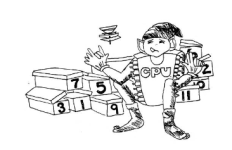
Thanks for the explanation - I think I get it - better than I did back in the 80's anyway. The ZX Spectrum machine code book confused me far more with elves counting on their fingers.1689389155219.png
I've been using the Lance Leventhal 6809 book, baby steps, but using an online assembler makes it easier to play along.
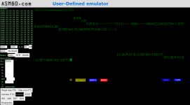
I did some programming with the ASM80 site - compiled ok but had some issues running it - I think I need an add in a java "terminal" plug in.

After that, I tried a few hardware experiments, the belt had fallen off my 8" Drive 0, now it turns at least but still will not load the head and seek.
I confirmed the I/O bus locations by adding a parallel card at port 2. This changes all the 37's to 0's in the range FCD0-FCD7 - so it really is 8 bytes per port !
I think the parallel port, printer / cassette ? is addressed through port 7 ( FCF8/FCF9).
 
You don't need any 'plug in' to get the asm80 simulator terminal to run. You just need a configuration file to tell asm80 how your terminal interface behaves.

I will pull one out I did for my Cromemco and see if we can 'buthcher' it...

Dave
 
Here are my MS6809.emu and ECHO.a09 files (contained within ECHO.zip).

The MS6809.emu file is the emulator (containing 64K RAM and a 6850 ACIA at addresses 0xFCF4 and 0xFCF5) and ECHO.a09 is the echo program source. Notice the addition of a ".engine" assembler directive. Thinking about it now - perhaps I shouldn't have configured 64K of RAM - as it overlays the I/O. However, it does seem to work...

EDIT: I set the emulator's RAM configuration to the following within the MS6809.emu file and the terminal emulation is much quicker!

Code:
memory.ram.from 0x0000
memory.ram.to   0xfbff

Copy the two files into ASM80.

COMPILE (well) ASSEMBLE the ECHO.a09 file.

RUN the EMULATOR [F10]. Click on the BLUE DEBUG and then RUN.

Type characters and watch them echo on an old-fashioned glass terminal. Be aware though that the emulator is fairly slow - so if you type fast, all bets are off...

The emulator seems to 'know' where the program starts. Let me check that one out though. Yes, the emulator automatically starts where the program starts. You can also STOP the program and single step it. You will see the register values and a disassembly of the instruction it is either about to process - or has just processed.

EDIT: I tried this with my cromemco file and it starts running automatically. This ECHO program does not start running automatically - so I wonder if it requires the correct reset vector including?

Dave
 

Attachments

  • ECHO.zip
    944 bytes · Views: 4
Last edited:
Well done.

I don't think the emulator is as refined for the 6809 as it is for the Z80. For example, there are no registers displayed in the debug window...

Still, something is better than nothing!

Dave
 
Well, I need do some more Assembly programing like how to write a "hello world" program, for the 6809 system.
But I should really be able to work that out on my own. needs a loop until it hits "04" (not sure why 04 is used at the end of an ASCII message string ?)

Then it's back to trying to get TSC FLEX/09 up and running on the MSI6800/GIMIX6809 system.

1, ultimate goal - boot Flex/09 from 8" floppy disk and have both 8" drives working.
2, intermediate step - setup the floppy controller to use a 5.25" drive to boot any flex disk to prove the floppy disk controller can read disks, or boot from a GOTEK 5.25" floppy emulator with flex format *.DSK images on the USB stick. The Flex user group site has a lot of *.dsk files.

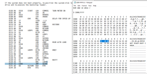
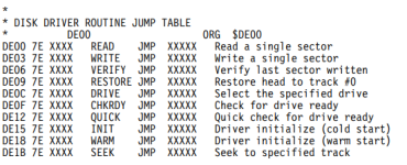
It looks like we have a bootstrap loader at the beginning of the monitor "BOOT" at E000, probably called by the "FLEX" command. This makes both the 8" disks spin - presumably looking for a boot sector #1, track #0 on the drive. The bootstrap should load into C000 then execute there ?
and look at this below ! lots of FCC0 and C000 (notepad is FLEXBUG)

1689564943915.png
I think you already disasembled this. I need to look back through the "reading 2716" roms thread.
 

Attachments

  • 1689562872619.png
    1689562872619.png
    56.4 KB · Views: 0
  • 6809fadg flex adaptation guide (1).pdf
    227 KB · Views: 1
  • 1689563109280.png
    1689563109280.png
    21.9 KB · Views: 0
  • 1689564385871.png
    1689564385871.png
    18 KB · Views: 0
>>> not sure why 04 is used at the end of an ASCII message string?

By convention.

They could have chosen any character - or bit 7 set on the last character if they wished.

ASCII 04 is EOT (End Of Transmission) by definition, so that got used.

Dave
 
Back
Top