• Please review our updated Terms and Rules here

My project: The SeaOtter Essentials Prototyping Computer

80186 Enthusiast

Experienced Member
Joined
May 18, 2023
Messages
53
WARNING: lots of text and images!!!​
Specs:
  • CPU: Intel 80188
  • RAM: 640k SRAM
  • ROM: W27C512-45Z 64K EPROM
  • VDP: TMS9918A
  • VRAM: 16k SRAM
  • Keyboard Controller: Intel 8279
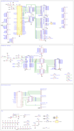
Schematic:
Schematic_SO 8-Bit Essentials Prototyping Computer_2023-07-11.png
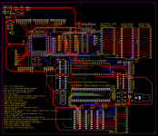
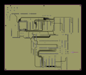
all PCB layers (No GND planes)
PCB_PCB_SO 8-Bit Essentials Prototyping Computer_2_2023-07-04.png

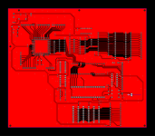
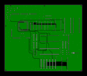
All PLB layers (with GND planes):
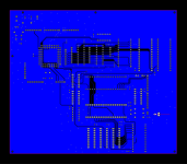
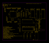
TopSilkLayer.pngTopLayer.pngInner1.pngInner2.pngBottomLayer.png

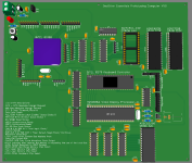
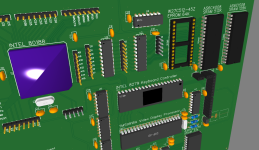
PCB 3D View:
Screenshot (136).pngScreenshot (137).png

Main Text of this Post:
Hello! after some time of trial and error, I've made this PCB! In my previous posts, I've asked questions on how the CPU should be wired up to the VDP and Keyboard controller, after receiving a handful of help, I was able to combine all of my knowledge into one schematic! after that, I made this PCB!

If you look at the image that shows all of the PCB layers with no GND planes, you can see a lot of vias that don't appear to be apart of any trace. That's because those are grounding vias! They help provide a stronger GND signal to areas where GND cant reach, so I tried to place them wherever grounding signals were needed! I've seen other PCBs have these (Like hard drive PCBs for an example). however, you can see that the CPU was used to be labeled as the CMOS version. I changed the Label after I found some regular 80188 CPUs on eBay that were cheaper than the CMOS variants.

Why did I call this the "essentials" prototyping machine? Because to me, the essentials to a computer is simply a keyboard controller and Video output. The last PCB I have to make is the Keyboard PCB. I still need to make the Keyboard layout, I'll make a different post about that in the future. After I create the Keyboard Layout, I'll study x86 assembly more closely and write a program that displays whatever symbol I type on the keyboard, a pretty simple test if you ask me. Why is this computer called the "SeaOtter"? I was at SeaWorld and I saw a SeaOtter and I thought "Wouldn't be cool if I called my Computer project series that?". The computer model name itself is SeaOtter I188-640

Side Project: Installing the 8086 x86 version of MSBASIC on this computer, that should be a pretty amazing test to see if my computer is ready for an OS or not. Imma hope it works. Let me know if this is possible or not!

As always, if you see somewhere I messed up, either in the Schematic or PCB design, please tell me in the comments below! Any help, information and advice will be thanked and appreciated! Thank you guys for reading! :)
 
I've been thinking about the kind of Logic chips (LS, HC, HCT ect) I'll use for my 80188 computer project. I need a type of logical chip that can handle multiple outputs at a time without - catching fire. I don't believe the 74LS series chips can do that.

Does anyone have any advice about this?

As always, any help and advice will be thanked and appreciated in advance! Thank you guys for reading!
 
I've been thinking I should switch to 74HC/74HCT series logic chips for the low power and current consumption because I want this computer to run from a single 5v power supply, but I'm also considering the 74AC series because they can handle extremely fast logic up to 120Mhz.

It's just hard to find 74LS series chips because they're no longer in production, and modern drop-in replacements are better, except for the fact that 47LS series chips have internal current limiting resistors - but it'll be better if I used the 74HC/HCT series chips if I wanted low current anyways.

There's just a lot on my mind about this.
 
Mouser (and others) has just about an 74LS chip that you might need. Some others places may be selling recycled or even fake chips and the big auction site is iffy if the chips are coming from overseas. Not saying that you should use LS chips, but just that they are available. Some years ago I purchased a Akro Mills storage case full of 74LS chips sold by a private seller on THE auction site. So I have a lifetime supply of many of these chips.
 
Yes, only purchase from 'trusted' sources.

When trying to get your own design running, the last thing you want to be bothered about is faulty, fake or substandard components!

Dave
 
I've been thinking about the kind of Logic chips (LS, HC, HCT ect) I'll use for my 80188 computer project. I need a type of logical chip that can handle multiple outputs at a time without - catching fire. I don't believe the 74LS series chips can do that.

Does anyone have any advice about this?

As always, any help and advice will be thanked and appreciated in advance! Thank you guys for reading!

Please explain in more detail what you have in mind with the statement "I need a type of logic chip that can handle multiple outputs at a time...". Different technologies within the 74 series provide different capabilities in terms of logic levels, speed, power consumption, input impedance, and output drive current. However it is not correct to say that in general 74LS series chips are "unable to handle multiple outputs".

I have looked at your current 80C188 project design, which currently uses ten LSTTL support chips. Relatively speaking the power consumption will be pretty small - that entire board will easily run from a small 5V power source. For some reason your design uses the 74LS573, which was never a commonly used part and hence is difficult to find. The 74LS373 is functionally identical with a different pinout, and is a very commonly used part that is easy to find. If you want to stick with the '573 pinout, then consider the 74HCT573 or 74ACT573 - these parts are easy to find.

Most 74LS parts are still in current production, and they are very easy to find. I suggest you buy all your active logic components from factory distributors like DigiKey, Mouser, and Newark. If you look at their web sites, you will find they have current stock for most 74 series parts (including 74LS).
 
If you want high drive capability, you might look at the 74ABT or 74BCT family. CMOS-bipolar hybrid devices with high output current capability--TTL level compatible. 64ma Iol should be enough for just about anything. Tailored to bus drive applications. I use them on my Pertec controller design.
 
If you want high drive capability, you might look at the 74ABT or 74BCT family. CMOS-bipolar hybrid devices with high output current capability--TTL level compatible. 64ma Iol should be enough for just about anything. Tailored to bus drive applications. I use them on my Pertec controller design.

...which is why we need to know what he is actually concerned about. His current 80C188 SBC design requires the LSTTL logic to drive an internal bus with 3 RAM chips, a keyboard controller chip, and a video display chip - which is well within the drive capability of LSTTL. There is no external bus support, and there are no external parallel outputs.
 
For some reason your design uses the 74LS573, which was never a commonly used part and hence is difficult to find. The 74LS373 is functionally identical with a different pinout, and is a very commonly used part that is easy to find. If you want to stick with the '573 pinout, then consider the 74HCT573 or 74ACT573 - these parts are easy to find.

Huh. I have a tube of LS573s and never knew they were "hard to find" when I bought them. (If you're dinking around on a breadboard the '573's pinout is so much nicer than the '373.) But it seems like I have more HCT lying around anyway.

I need a type of logical chip that can handle multiple outputs at a time without - catching fire. I don't believe the 74LS series chips can do that.

What is "multiple" and "catching fire"? The fan-out for LS logic outputs to LS inputs is usually good for around 20 or so, and if you really needed to stretch it you could strategically add some pull-up resistors. If you're driving real LS devices (FWIW, note that most peripheral/RAM/whatever chips are *not* LS chips, they're *MOS devices with LS-level inputs, so their required drive currents might not necessarily be the same) LS actually has better drive than HCT does. (HCT *inputs* draw basically no current, so if you were to drop a pull-up resistor in there you could probably drive *hundreds* of HCT inputs from an LS output. But on the flip side, HCT can't drive "down" as hard as LS, so HCT can only handle driving around 10 or so LS inputs.)

It sort of feels like the OP might be overthinking things a bit here.
 
Huh. I have a tube of LS573s and never knew they were "hard to find" when I bought them. (If you're dinking around on a breadboard the '573's pinout is so much nicer than the '373.) But it seems like I have more HCT lying around anyway.

I have no doubt you could easily find 74LS573s when they were in active production. This is one 74LS part that is no longer in production, which is why DigiKey and Mouser no longer have them in stock but they are available from reputable retailers like Arrow and Rochester as "new old stock". They are also available from several other retailers (and of course eBay) that specialize in selling out of production components. So yes they are available - but you do have to look around a bit.
 
I have no doubt you could easily find 74LS573s when they were in active production. This is one 74LS part that is no longer in production, which is why DigiKey and Mouser no longer have them in stock but they are available from reputable retailers like Arrow and Rochester as "new old stock". They are also available from several other retailers (and of course eBay) that specialize in selling out of production components. So yes they are available - but you do have to look around a bit.
OTOH, 74F573 and 74ALS573 are readily available in DIP as well as SOIC packages. And, as previously mentioned, 74ABT573 as well. 74LS technology is pretty much obsolete, superseded by these higher spec families. And yes, you can mix families.
 
Hmmm... I'd go ahead and latch A8-A15. The processor drive capabilities are much less than the LS573, and it will isolate the address lines from the CPU so when you go poking around with your scope and slip you won't blow up your CPU...

A diode across R5 (cathode to +5V) would help discharge C6 more quickly on power-off.

The SW1 schematic symbol doesn't make any sense.

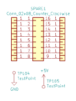
When there is unused space on the board, add spare (unused) DIP footprints (pads) so that if you have to or want to make a mod you won't have to glue the chip(s) upside down on the board or make a new version of the board... Example (KiCAD) shown below.
spare.png

In this case, the footprint of the Conn_02x08 would be a DIP16 and the test points and square boxes with a single pin are just through-hole pads of your choice...

Also, I hate seeing GND pointing up or sideways, +5V pointing down or sideways. +5V points up, GND points down. Eliminates confusion as to whether the schematic is correct or not (that's pointing up, but it says GND - did he mean +5V? *think* *think* *think* No, I guess it's really GND)

On the PCB, the memory chips are mounted upside down relative to the TTL chips. It's really best if they point in the same direction. Otherwise, someone not paying attention might mount them the wrong way round. Similarly, U4 and VDC1.

Routing on inner PCB layers is not a good idea. You can't probe them and you can't cut them if you discover you've made a mistake and need to reroute a signal. Use top and bottom layers for traces and inner layers for +5V and ground planes.
 
Huh. I have a tube of LS573s and never knew they were "hard to find" when I bought them. (If you're dinking around on a breadboard the '573's pinout is so much nicer than the '373.) But it seems like I have more HCT lying around anyway.


What is "multiple" and "catching fire"? The fan-out for LS logic outputs to LS inputs is usually good for around 20 or so, and if you really needed to stretch it you could strategically add some pull-up resistors. If you're driving real LS devices (FWIW, note that most peripheral/RAM/whatever chips are *not* LS chips, they're *MOS devices with LS-level inputs, so their required drive currents might not necessarily be the same) LS actually has better drive than HCT does. (HCT *inputs* draw basically no current, so if you were to drop a pull-up resistor in there you could probably drive *hundreds* of HCT inputs from an LS output. But on the flip side, HCT can't drive "down" as hard as LS, so HCT can only handle driving around 10 or so LS inputs.)

It sort of feels like the OP might be overthinking things a bit here.
What I meant by multiple outputs: Address Like 0 is connected to the Keyboard Controller and VDP, and in the future there could be more address lines from that latch IC connected to more Components.

Catching fire: Incompatible components = Boom

Yea I was overthinking some things about this.
 
If you want high drive capability, you might look at the 74ABT or 74BCT family. CMOS-bipolar hybrid devices with high output current capability--TTL level compatible. 64ma Iol should be enough for just about anything. Tailored to bus drive applications. I use them on my Pertec controller design.

I can't thank you enough for this advice!
Are there any specific differences between the 74ABT and 74BCT I need to know about Before I make a final decision however?
 
What I meant by multiple outputs: Address Like 0 is connected to the Keyboard Controller and VDP, and in the future there could be more address lines from that latch IC connected to more Components.

Catching fire: Incompatible components = Boom

Yea I was overthinking some things about this.

Look in any vintage computer made out of 74LS and you'll see fan-out in the tens and twenties everywhere. (Take for example a bank of memory made of 1-bit wide RAMs; that's 8 devices fanned off of each address line LS output right there *alone*.) And if you're really concerned you can strategically add additional layers of buffers as needed. You don't need exotic BiCMOS bus drivers for a computer that fits on a single board and runs at less than 20mhz, it's just not a thing(*).

(* If you're planning for speeds more than 10mhz or dealing with multiple layers of buffers it is worth strategically going with "F" or "ALS" so you're not adding up too many layers of propagation delay, that's a far more likely concern than fan out for a project of your scale.)
 
What I meant by multiple outputs: Address Like 0 is connected to the Keyboard Controller and VDP, and in the future there could be more address lines from that latch IC connected to more Components.

Catching fire: Incompatible components = Boom

Yea I was overthinking some things about this.

As has been pointed out, LSTTL outputs can easily drive up to 10 LSTTL inputs. A bus driver (like the 74LS573 you specified) can do even better. Suffice it to say you are overthinking this - your design does not come close to exceeding the capabilities of LSTTL, and leaves plenty of leeway to add several more components. To put things in perspective consider the design of the original IBM PC - it made extensive use of LSTTL, and supported the entire ISA bus using simple LSTTL bus driver ICs.
 
Back
Top