• Please review our updated Terms and Rules here

My Rusted PET8032 with busted CRT ...continuous resurrection

You might also want to check D752 on the E400 (400V DC) supply.

This feeds the focus and sub-brightness potentiometers.

I guess you have removed C754 to gain access to the diodes?

Dave
 
Thank you Dave/Hugo....will try to source the diodes locally. I noticed that the electrolytic 47uf/250 is also getting hot so I will to pick that one too

Yes ...I took that capacitor out to test it and notice a slight bulge by my Chinese tester read 50uf sp I thought it is ok
It will be awhile cause those BY448/228 are not locally sourced.
 
Last edited:
Thank you Dave/Hugo....will try to source the diodes locally. I noticed that the electrolytic 47uf/250 is also getting hot so I will to pick that one too

Yes ...I took that capacitor out to test it and notice a slight bulge by my Chinese tester read 50uf sp I thought it is ok
It will be awhile cause those BY448/228 are not locally sourced.
They have the BY448 at Digikey:


They are a lot more common in Europe & the UK though. It had been so long since I bought a box if them, I cannot remember where I got them, probably the bay. They are handy to have because they out-spec practically every other diode of that type, so you can use them as a go to generic replacement and it saves a lot of time.

You could just use a UF4007, much easier to get, though rated at 1A, though I think the V06E was 1.1A, prob ok.
 
I think I can pick that UF4007 locally. I was going to ask also about 1N5408 rated at 3A/1000volts but it is a common rectifier ( not a damper or Ultra fast one). My local store has it and I am planning to go there ( it is in downtown Vanvouver ~ 45 minutes drive).

EDIT: They also have this diode-fast-recovery-rectifier-uf5404-400v-3a
Well they have UF4007 so I will settle for it...higher voltage but only 1A
 
Last edited:
So a BIG Disappointment today.
I got my diodes and capacitor, installed them and tested. However, I got BLANK Screen.
Expected brightness voltages are there, but this time I don’t get any horizontal beam or anything. My vertical/horizontal/video signals are present. However the expected 194V at the positive side of D721 is missing (1.~~volts). Transistors show OK on tester, continuity on Flyback windings got continuity. Did I damaged the flyback yoke by shorting the end to discharge the voltage prior to taking out the pcb assembly.
Checked all soldering done too.
I am at a loss now.
 

Attachments

  • 8082C924-6478-4F8C-959D-3ED4C1E1179E.jpeg
    8082C924-6478-4F8C-959D-3ED4C1E1179E.jpeg
    1.9 MB · Views: 3
So a BIG Disappointment today.
I got my diodes and capacitor, installed them and tested. However, I got BLANK Screen.
Expected brightness voltages are there, but this time I don’t get any horizontal beam or anything. My vertical/horizontal/video signals are present. However the expected 194V at the positive side of D721 is missing (1.~~volts). Transistors show OK on tester, continuity on Flyback windings got continuity. Did I damaged the flyback yoke by shorting the end to discharge the voltage prior to taking out the pcb assembly.
Checked all soldering done too.
I am at a loss now.
Check the notorious fusible resistors, R751 & R752, R753 and replace them if they are open.

You don't have to discharge or short anything out on these VDU's, just leave them overnight before you work on them.
 
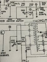
PS: .....''the voltage on the cathode (positive side of D721) is not supposed to be 194V DC, it is a narrow peak pulse (the flyback pulse) with a base close to zero volts and only about 10uS wide and it peaks to around 200v. This pulse passes via the fusible resistor R753, and is peak rectified by diode D753 (though on my schematic it looks like D253 in the label) and stored as a DC level on the capacitor C753, which is where you should find about 190V DC.

It is misleading that they have named that point on the schematic on D721 as 194V DC. If you check there with a scope (scope on 50V/cm with a x10 probe), you would find that the voltage that you see on the cathode of D721, is almost identical to that on the collector of the HOT (Test point 18), just a little higher in level. There are only a few turns on the flyback transformer between its pins 1 & 3.

Shorting out the CRT to discharge it can potentially cause trouble, it won't damage the flyback transformer, but it can damage transistors on the pcb, depending on the ground point that it is discharged into, because the peak currents can be surprisingly high, and the stored energy for a CRT of this size can be in the order of 50mJ to 150mJ, this is not enough to harm a person as a single discharge, aside from getting a fright, but enough to damage transistors & IC's if present. If you did get a zap from it, it would feel like a single pulse from a car spark plug or lawn mower plug.

(The CRT bulb capacitance is in the range of 500pF to 1000pF and if charged to 12kV the stored energy is (12000)^2 x 1000 E-12 /2 = 0.072 J = 72mJ )

For most repairs, you don't need to go under the anode cap, and the CRT charge stays safely in the CRT bulb. If you want to go under the anode cap within minutes of turning the set off, it is better to discharge the CRT with an EHT probe, which has a very high value resistor in it, typically 100 M Ohm or greater and limits the peak current to a very low value much less than a milliamp. The EHT rectifier in the flyback assembly has a non zero reverse leakage, so the other way is just to leave the set un-powered overnight and the CRT bulb charge largely self dissipates and you can go under the anode cap when the charge has largely depleted to a low value on its own.
 
Last edited:
Well, after a month of hiatus, waiting for a transistor (high voltage) that is the only one I suspect of getting damaged by my ‘shorting’ of the anode to CRT, I finally received a replacement.
Sadly it is not the problem. One thing I notice is that when I power the 8032 on, I see small momentray sparks at the bottom of the pcb board ( where most tracts are ). I have gone thru possible suspect parts but to no avail. I suspect I may have damaged the flyback transformer. Could I possibly blew that “diode” (EHT rectifier?) inside it as drawn in the schematics.
I have now just about given up on the CRT and just use my composite adapter with outside LCD monitor.

Those sparks sound bad, there should never be anything visible like that on the pcb tracks. Can you take a video of that ?

It is important that the external aquadag (conductive coating) on the CRT is properly grounded.

Usually the EHT rectifier inside the flyback transformer and the flyback transformer itself are fairly robust. It is a matter of checking the various voltages and signals with the scope, to try to get to the bottom of where the problem/s are.
 
Back
Top