• Please review our updated Terms and Rules here

Need help when use isa-to-usb card in IBM 5160!

I took the 3kB BIOS file, padded it to 4kB, added correct number of blocks and checksum. Try it.
 

Attachments

  • CH375ROMedit2.zip
    1.7 KB · Views: 10
https://www.lo-tech.co.uk/product/lo-tech-isa-compactflash-pcb/

This is really easy to solder, all through hole. Probably easier than modding your existing card too.

Too bad it doesn't come with a component bag anymore so you have to find and buy all parts separately.
Please share your ideas ,maybe this card can come to life with your help.

My ideas are for a brand new card from scratch, not for fixing the existing card. I suggest doing the (very easy IMHO) mod already suggested for fixing the address decoder, and trying the new bios file as well.
 
CH375ROM output a line "Press CTRL to start E-DISK",so I think even the rom size byte is 3kb (not a multiple of 2 KB),XT bios still called the rom bios.
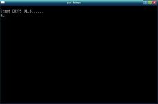
Yes. The 2 KB issue only causes a problem after CH375ROM has been executed:

1. 5160 motherboard POST starts its search for BIOS expansion ROMs.
2. POST finds your CH375ROM and executes it.
3. POST resumes its search for BIOS expansion ROMs, but because CH375ROM was not a multiple of 2 KB, the POST is now 'confused'.
4. 'Confused' POST thinks that it sees a BIOS expansion ROM at F6400, and because of the non-zero checksum, displays "F6400 ROM".
5. POST resumes its search for BIOS expansion ROMs.
6. 'Confused' POST thinks that it sees a BIOS expansion ROM at F8400, and because of the non-zero checksum, displays "F8400 ROM".
7. POST resumes its search for BIOS expansion ROMs.
And so on ...
 
According to a sticky thread IBM-PC-XT-5160-BIOS-versions there are four versions of bios,only the last two support 720k floppy.I'm afraid mine is not that version,you can see the U19 chip picture I upload before ,it has a part number 5000027.I guess boot from.3.5" 720k floppy may not work.

It'll work, See this page on Modem7's site.

Edit: Argh! i just remembered you said you're running DOS 2.1, It won't work, You'll have to upgrade to at least DOS 3.3 or better, The Dos USB driver requires Dos 3.x according to the readme anyway.
 
Last edited:
JH, would it be possible to tweak the ROM to use IO port 300h as a base address?


Yes of course. Just change locations 0x38-0x39 with the address of the I/O port you want (default 0x260), and adjust the last byte of the ROM to get a 8-bit checksum of 0.
(and of course change the address decoding to actually map the usb chip to that address)
 
I'm putting together a board with a ch376 on it, should be ready to test shortly, maybe I could persuade you to post a patched ROM as that's not something I'm too familiar with :)
 
Yes of course. Just change locations 0x38-0x39 with the address of the I/O port you want (default 0x260), and adjust the last byte of the ROM to get a 8-bit checksum of 0.
(and of course change the address decoding to actually map the usb chip to that address)
On the v1.3 bios that i posted the i/o address is located at 0x38-0x39.
However on the v1.5 bios that ineverland and you posted the i/o address is located at 0x36-0x37.

Thank you for your advice.I never soldered anything before ,that's why I didn't choose XT-IDE cards,they have no working card on sale.But this time I want have a try.Please taught me how to do it if you have time :super:
(edit)Is there a another way to do it ,like reporgram or replace the little chip in the bottom left?
If you have an hour to spare here is a two part tutorial on how to solder https://youtu.be/J5Sb21qbpEQ https://youtu.be/fYz5nIHH0iY.
If you want to try it its best to practice on some old cards, when your ready for the real deal remember to only solder the very top of the ISA contacts so it will still fit the motherboard.

Reprogramming the address decoder in the bottom left is useless because the needed address bits are not connected to anything as you can see in the picture i posted, also all the pins of the address decoder are already used.
 
On the v1.3 bios that i posted the i/o address is located at 0x38-0x39.
However on the v1.5 bios that ineverland and you posted the i/o address is located at 0x36-0x37.

That's true, I hadn't checked. Easy enough to spot though in a hex editor.

I'm putting together a board with a ch376 on it, should be ready to test shortly, maybe I could persuade you to post a patched ROM as that's not something I'm too familiar with :)

(edit) here's the latest ROM, padded to 4k, I/O address changed to 0x300 and checksummed.

I'm also contemplating a board or two based on those pre-made CH375/CH376 modules such as http://www.ebay.com/itm/191605145574?_trksid=p2060353.m2749.l2649&ssPageName=STRK:MEBIDX:IT and http://www.ebay.com/itm/1pcs-CH376-...-Board-2730-/291134788833?hash=item43c8fc54e1
I have a few of these http://www.ebay.com/itm/130350912819?_trksid=p2060353.m2749.l2649&ssPageName=STRK:MEBIDX:IT to use for prototyping; they have enough space for glue logic and EPROM or flash, and I'm thinking of putting a header for the USB module to be plugged into, similar to plugging a wavetable into a soundcard. :) The BIOS address could be selectable in the same way as on your ISA ROM board. Perhaps a fancy I/O address selector, but that would need to change the presetaddress in the firmware as well. My ideas for that would be, either:
1. have several copies of the BIOS in an EPROM/flash chip, and changing the I/O address via switches not only alters the address decoding for the USB chip, but also selects a different BIOS image with a different I/O address. This seems the most feasible; or
2. Eh, forget about it; it's too complex to intercept just the reads from addresses 0x36-0x37 in the BIOS and dynamically generate different outputs based on a switch address selector.
3. even more outlandish is shadowing the BIOS in a SRAM at boot time, and modifying the SRAM contents on-the-fly. :p
 

Attachments

  • CH375ROMedit3.zip
    1.7 KB · Views: 10
Last edited:
Thanks for the files! I have the first list and will be modifying an ISA-CF PCB to test this. I'm sure you've seen the datasheet already, but my next thought is to integrate this into the XTIDE Universal BIOS. That BIOS uses a couple of KB of RAM for scratch config. Of course with flash we can re-write the BIOS anytime too. I'm pondering on single CH375, dual CH375 (one plugable external media socket) or perhaps one CH375 for pluggable module and CompactFlash for internal storage. It really depends on the performance.
 
It would be nice to have the XTIDE Universal BIOS support the CH375 and CH376 as an extra controller type then we can start thinking about designing it in to a card.

Something like an XT-CF-lite with dual CH375 would be my idea, have the CF and one USB on the bracket and the other USB on the inside.
Or change it to a CH376 so you have USB and SD in one controller, that way you can drop the CF interface.

If you want to go crazy put 2 USB, 1 CF/SD, 1 IDE, 1 DOC2000 and 1 floppy on a single card, then we would have the ultimate XT storage card ;)
Combine that with an COM, LPT, RTC, RAM and EMS card and the only thing that is missing is the graphics, audio and network card, that would make 5 cards with everything you ever want in a IBM 5150.
 
Thank the forumn,now I know much beter about CH375 card,5160 bios POSTprogress,option rom...
Back to the problem of booting from usb,I think neither address decoding nor wrong bios size is the real problem.
Because wrong address decoding may only cause you have just 96kb memory to use, XT can boot with that,but the card didn't make it.
Wrong bios size can cause XXXX ROM,but CH375 BIOS has already run,If it works,then I should boot correctly from usb ,but I'm not.

So I doute CH375 BIOS may has some compatible problems.It just returns to system BIOS after output a line,it seems that it didn't wait user to press any key or didn't read the right key scan code.
The v1.3 bios will stop the system for a long time and return(I post a picture before).I think that maybe the right thing the card should do.
I will disassemble the bios file to find out what the rom bios do after outpout "Press ctrl to start e-disk".
I look forward to seeing your test result too :)
 
Last edited:
Here's a disassembly of the latest bios (the real code, which starts at address 0x100 in the file).
 

Attachments

  • ch375romnew3.zip
    9.2 KB · Views: 10
Here's a disassembly of the latest bios (the real code, which starts at address 0x100 in the file).
Do you agree with me that the BIOS program has something wrong ?At least it should output more informations when some error occurred,not just return to system.
Hope someone can rewrite the rom bios:computer:
 
I have a glance at the assembly code:

Code:
seg000:0100 ; ---------------------------------------------------------------------------
seg000:0100
seg000:0100 loc_100:                                ; CODE XREF: seg000:0003j
seg000:0100                 pushf
seg000:0101                 push    ds
seg000:0102                 push    ax
seg000:0103                 push    bx
seg000:0104                 push    cx
seg000:0105                 push    dx
seg000:0106                 push    si
seg000:0107                 push    di
seg000:0108                 mov     bx, ax
seg000:010A                 mov     cs:word_18, bx
seg000:010F                 xor     ax, ax
seg000:0111                 mov     ds, ax
seg000:0113                 mov     si, 1E8h                                   ; "Press CTRL to start E-DISK"
seg000:0116                 call    sub_22D                                    ; Print a string with int 10h
s[COLOR="#FF0000"]eg000:0119                 test    ds:byte_417, 4                             ; check CTRL key?[/COLOR]
seg000:011E                 jnz     short loc_123                              ; Jump to do real job
seg000:0120                 jmp     loc_1DF                                    ; Jump out and return
seg000:0123 ; ---------------------------------------------------------------------------

(edit)what is the meaning of the red line?
 
Last edited:
I debugged the beginning of this bios code, and confirmed that the rom just returns to system after a test just like the red code I posted.
the "real code" has never been executed.
 
I modified some instructions to force bios run into real code,and get this output:
but it seems not run correctly.
 

Attachments

  • 123.JPG
    123.JPG
    11.4 KB · Views: 6
Back
Top