• Please review our updated Terms and Rules here

Need help with "unresponsive" Teletek FDC-1C all in one computer-on-a-board.

The boards burned up traces because the caps were bad. Shorted capacitors (electrolytic and tantalum) are par for the course on old gear. Unfortunately, that shorted cap, before it goes kablooie, will sometimes take a trace or two, if the trace is thin enough. It happens and there's nothing you can do about it, short of putting a fuse on each board.

Okay, so the CPU is doing something. The issue we should find out is if the SIO chip is being addressed. If the CPU is polling and waiting for a return, it'll have to access the chip to see if there's any data present. I don't have the Teletek schematic in front of me, but no matter.

Pin 35 of the SIO (or DART) chip is the chip enable--you should see this pulsing. You should see a steady waveform on pins 13 and 14 (receive and transmit clocks for the "A" side). This will at least tell you that the PROM program is setting things up.
 
Here's what I know... (?)(Never mind)

OK, here's what I can relate and show you pix of:

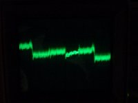
SIO pin 35 .5 uS/div., .1V/div. No higher voltage signals seem to be there, just continues repeating the same pattern.
SIOpin35.jpg
dProbe says; high

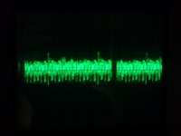
SIO pins 13 & 14 disp[layed alike:
Slowed one detent to 1uS/div., and same .1V/div. The faint tall spike that goes off scope is shown the bottom picture; is this just noise?
SIOpins13-14.jpg
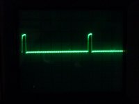
Here they are at 2V/div, these pulses are apparently almost 4 volts?
SIOpins13-14 2V.jpg


dProbe says; On TTL both High and Low light, I switched to CMOS just to see what would happen, and only the Low lit.

I hope that means something.
Bruce
 
Well, the pin 13 and 14 should be the same thing; that's the receive and transmit clock. I see, what, 7 uS period = 143KHz? Since the SIO has a divide-by-16, that gives around 9K baud? Well, I'm only doing an eyeball guesstimate.

Try looking at pin 35 at 2V/div. Should be a constant high with an occasional low spike as the CPU checks for a character. I'm assuming that your probe has a pulse-stretcher and LED to indicate a pulse, so you should see that LED flashing when you check that pin.

Pin 20 should have the CPU clock on it (2/4MHz).

When you press ENTER/RETURN on the terminal, you should see the pulse train go by on pin 12 (I'm assuming that terminal I/O is using the "A" side of the SIO chip; if using the "B" side, you should see a pulse train on pin 28.

If the CPU monitor program is responding, you'll see the answering pulse train on pin 15 (A side) or pin 26 (B side).

Oh, and if the "B" side is being used, a baudrate clock x 16 should be on pin 27.

If you see received pulses at the SIO, but no answering pulses, and pin 35 remains stubbornly high, it begins to look as if your EPROM program may be bollixed (my best guess).
 
Well, the pin 13 and 14 should be the same thing; that's the receive and transmit clock. I see, what, 7 uS period = 143KHz? Since the SIO has a divide-by-16, that gives around 9K baud? Well, I'm only doing an eyeball guesstimate.
Try looking at pin 35 at 2V/div. Should be a constant high
Yes, about 4V
with an occasional low spike as the CPU checks for a character.
that part's not happening
I'm assuming that your probe has a pulse-stretcher and LED to indicate a pulse, so you should see that LED flashing when you check that pin.
Seems I still have the wrong probe! HiLo LEDS, switch TTL/CMOS, switch Mem/Pulse. There is a yellow led that is associated with Mem mode, but nothing happens on #35. #34 and others will turn it on, however.
Pin 20 should have the CPU clock on it (2/4MHz).
Solid pulses, about .25 uS cycle
When you press ENTER/RETURN on the terminal, you should see the pulse train go by on pin 12 (I'm assuming that terminal I/O is using the "A" side of the SIO chip; if using the "B" side, you should see a pulse train on pin 28.
#12 it is; If I press different keys and hold them down to repeat I can see it lock onto the different pulse patterns, trace holds high, the key pulses drop back to 0V.
If the CPU monitor program is responding, you'll see the answering pulse train on pin 15 (A side) or pin 26 (B side).
That is not happening, either
Oh, and if the "B" side is being used, a baudrate clock x 16 should be on pin 27.
This one's on A side
If you see received pulses at the SIO, but no answering pulses, and pin 35 remains stubbornly high, it begins to look as if your EPROM program may be bollixed (my best guess).

Rats,
Bruce

(Well, I'm off to my local Teletek outlet store for a new EPROM with a working monitor program.) Oh, -wait...
 
I'd guess that you guessed I was not going to get such an ethereal piece...

I'd guess that you guessed I was not going to get such an ethereal piece...

~of software on a chip from Radio Shack.

I am going to de-solder my power supply, if necessary, -but one way or another make it well, and well within specs. This chassis was the one that toasted a trace on a couple of boards I was testing, but I tend to hope that was old bad caps, as Chuck suggested. The scope data showed some very, very low AC in the -16V line, -19V in my case at present, but several articles I have since found at least imply that it is within tolerance at the outside, with temps in the V.R.s being the risk. I have no experience here, yet!

I am sure I can get the PSU to behave though.

---Since I have no requirement to follow any "collectible" guidelines, do any of you have recommendations on whether I should build a switching PSU with modern component modules? It might be a good interim solution...

A biggie:
If there are no operating FDC-1C systems, and no surviving humans who had the code, then I must write it myself? I don't know if I can accomplish that at age 63, -my memory is more volatile than non-volatile, though I am willing to try.

I don't know where to start.

One request I have is, if any of you within "reasonable" driving distance of Amelia Island, FL have a running S-100 system, could I try my VT-520 terminal on your system, just to see if it is a working example of a term. I have more variables than I can deal with at this point.

I know you guys broke a record or two in number of posts trying to help me get this thing running, and this is appreciated more than you'd imagine.

Thanks for all of that!
Bruce
 
Well, you're at sort of an advantage--you have documentation for the board as well as for the chips. So, writing a simple program to input a character from the terminal and echo it back might be a good place to start.

Unfortunately, I'm almost as far away in the continental US as one can get from you...
 
Bruce;
Please forgive me for my earlier comments. I had not looked at the picture. Your board appears to be a disk controller, not a Systemaster. My experience with the Systemaster leads me to believe it is likely a very capable disk controller which includes serial and parallel IO for console and printers.
 
One request I have is, if any of you within "reasonable" driving distance of Amelia Island, FL have a running S-100 system, could I try my VT-520 terminal on your system, just to see if it is a working example of a term. I have more variables than I can deal with at this point.
I sure wish I were in FL right about now ;-)

Just hook it up to any computer with a serial port and a terminal emulator program or equivalent (e.g. Hyperterm), connect them with a null modem cable or adapter and type merrily back and forth.
 
Back
Top