• Please review our updated Terms and Rules here

Nixdorf 8870 Quattro /25

Tesla44289

New Member
Joined
Apr 27, 2023
Messages
7
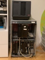
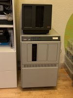
So there it is, my first mini, a Nixdorf 8870 Quattro /25 system. It came from a car dealership where it seems to have been used to control the gas station, at least according to the service logs, which also state that the computer was installed in early 1988. The lot included an external 8“ floppy drive and two Nixdorf DAP3 keyboards, but unfortunately no terminal…IMG_2677.jpegcamphoto_1903590565.jpeg

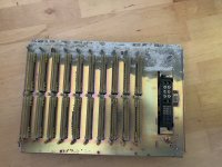
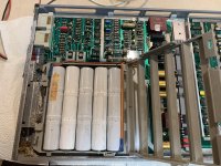
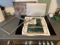
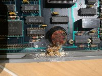
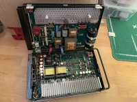
Of course the batteries in the UPS and PLU cards leaked and reeked havoc on the frame, but luckily the electronics only seem to have minor damage. I’ve already removed and will replace them, together with a couple of leaky caps in the (surprisingly beautifully constructed) power supply.IMG_2672.jpegIMG_2665.jpegIMG_2667.jpegIMG_2656.jpegIMG_2648.jpeg

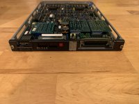
I find the PLU card to be quite interesting since it basically is a Z80 computer on a card, however haven’t been able to find any documentation for it. Hopefully the 68MB Fujitsu ST-506 hard drive runs at least long enough to pull a backup and has the corresponding software on it (although I still have to build one of those MFM backup cards from pdp8online)…
IMG_2698.jpegIMG_2699.jpeg
If anyone has more information, software or documentation for the Quattro /25 system please let me know! I‘ll of course Post an update as soon as I get running.
 
Last edited:
I run the website 8870Adventures.com

From left to right your system contains the chassis PSU.
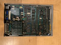
There are three plates (boards) stuck together. The left two are the CPU and I think will be a 1537 in your system. The black 25 pin cable goes to the status display and the other connector allows for an engineering diagnostic exerciser to be connected.
The next plate is the memory - typically 256, 512 or 1M but there are other combinations available.
Next is the 2536-02 a PLC2 board and you won't need that to get the system working.
The next plate is intriguing - it looks like a modem interface board but I'm not sure. We didn't use those typically in the UK.
After that is the 4 channel ALM (Asynchronous Line Multiplexer). This is where you connect the terminals/modems. Bottom connection is port 0 (master port), next up is usually the remote support modem, then either more terminals or V24 devices.
The next two are disk, SMC and floppy interface boards. I would have thought the right board was the SMC/disk interface as they usually share the same board, but there is only one cable.

On the inside of the door there should be some black stickers that give you the board numbers (1882-00 or 1882-01 etc), what they are and the DIP switch settings.

Boards can be placed in any other and whilst there can be empty slots at either end, the boards must be all together with no gaps between them. PSU is fixed in the left slot of course.

You can also remove the 8 1/2" floppy controller.
You will however need that 3038 plate; though you can remove the battery pack completely.
It was only there to keep the memory alive in event of a power failure, was only good for around 20-30 mins and these days a cheap mains UPS is better.
It's good practice to remove all the boards you can to reduce the load on the PSU.

If you do get it working, the best you can hope is a status "26" on the top status display; VDU does not reply. The red LED on the ALM for port 0 (bottom) will be flashing.
For a terminal you have three basic options a DAP4, a BA80 or a PC with a DAP emulation card and software.
You cannot unfortunately just connect a dump VT100 type terminal. When the system starts it attempt to hold a handshake session with the terminal, where the terminal tells it what type of terminal it is, and
what type of workstation program it needs. The system will then download the workstation program to the terminal, then the system will start to boot properly.

The good news is that if you do get a status 26, it means there is an operating system and that's a big deal.
However, it's typical that as the system boots you start seeing disk allocation errors scroll up the screen and you are basically watching the operating system being deleted before your eyes.

If you do attempt to start it after servicing, watch it like a hawk. The retched boards are full of tantalum capacitors that go short circuit. I lost a 3038 board due to one of those.

You've obviously managed to remove the front cover, often at the bottom of the inside of the door is a blue pocket that contains a set of keys. These should fit the start key switch at the top.
If there are no keys, you can start the system manually by flipping the switch on the main PSU. I think you push it down and then move it back to centre (it's been a while).

Not sure if you got any backup tapes with it, if so, the ones to guard with your life are S0, S1, S2 etc. These contain the operating system.
However the SMC drive will almost certainly be unserviceable. There's a rubber roller that degrades and falls to pieces. Those drives were terrible when they were brand new.

Will be interested to know how you get on and you can always drop me a line via the Email address on my website if you need any help.
Good luck,
Joe
 
Hi Joe, I cannot thank you enough for your reply, very helpful for identifying the components in my system!
The next plate is intriguing - it looks like a modem interface board but I'm not sure. We didn't use those typically in the UK.
I think you might be right about that, there are multiple cables that leave the computer and terminate in a telephone connector, however the modem itself is missing, so the opposite ends of the cables are just dangling in front of the empty slot in the adaptor card. If I only knew what type of Modem belongs in there...
I would have thought the right board was the SMC/disk interface as they usually share the same board, but there is only one cable.
The hard drive unit doesn't have a cable coming out of it, it plugs into the backplane, maybe it's connected to the disk controller internally via the backplane somehow? I've already taken the HDD unit apart and it doesn't seem to have a separate internal controller, if I remember correctly.
If you do get it working, the best you can hope is a status "26" on the top status display; VDU does not reply. The red LED on the ALM for port 0 (bottom) will be flashing.
I'm hoping for that, although I've got to replace the leaky PSU caps first...
For a terminal you have three basic options a DAP4, a BA80 or a PC with a DAP emulation card and software.
I might be able to acquire a DAP4 from a hoarder in a couple of weeks, but I don't know what condition it is in, hopefully it's not completely trashed.
 
So Nixdorf liked using Racal and Quattro (which were just badged by them) modems.
I think they were set for 1200 baud with 1 start, 8 data and 2 stop bits giving an 11 bit word. I know that over the years we tried to use other much cheaper modems and could never configure them correctly.
They were just starting to move to 2400 baud but as far as I know, 1200 remained the most common; in the UK anyway.
In Germany I think everything was basically ISDN.

As you've seen your chassis has two backplanes. The bottom one is the logic backplane, and the top is a peripheral one. The two backplanes don't really interconnect except for power and I think a couple of control signals. This is deliberate to make the chassis and backplanes reusable for different machines.
As it happens the M25 machine is different from most 8870's in that it only has one PSU on the lower logic tier. Most 8870's have a PSU on each tier; be it logic or peripheral. The M25 (and the horrible M15) were designed as small office machines so had smaller backplanes than larger 8870s (M45, M75 etc).

All backplanes have IDC connectors on the edge that allow them to be daisy chained to other tiers or connected to controller plates. There should be a cable that runs from the peripheral tier backplane, down the edge, under the logic tier cage and up into to the front of the disk controller. The SMC drive only gets its power from the backplane; all the control signals are routed via the data cable that comes out the front of the SMC and plugs into the disk/SMC controller plate.

Finding a working DAP4 will be a challenge, and one where the lithium backup battery hasn't leaked and eaten everything even more so. However, you may be lucky. Also, like everything Nixdorf did, looks can be deceiving. A DAP4 is really just a chassis with a CRT. What makes it 8870 compatible is the PSU and processor board installed. The DAP4 was probably the most popular VDU Nixdorf did and whilst they look identical, they will have a different processor plate installed depending on the target system. In the UK that could be for an 8812, 8850, 8860, 8870, 8890. There are also some differences around the keyboards. If the keyboard has provision to accept metal security keys down the right hand side for example, it's probably not an 8870 keyboard so probably not an 8870 DAP4. But there are always exceptions. One of the DAP4s I had on my desk had one of these security keyboards. Needless to say, a DAP4 from one series of machine won't work (without a replacement CPU plate and possibly replacement PSU) on another series machine.

It may sound confusing but everything Nixdorf did was modular. In the UK the banks and building society's used 8860 BNC machines. The chassis for the 8860 BNC was never sold (in the UK) for anything other than 8860 use due to it's physical dimensions, but change the processor plate, remove a couple of the plates used for communications, add an ALME and chance a couple of jumps on the logic backplane and you had a working 8870 chassis. Engineers didn't have to carry spare, bulky and heavy VDUs around with them, just a selection of replacement PSU's and CPU plates. It was rare that a CRT actually failed.
And as you've probably realised, changing a CPU or any plate is a piece of cake. Pull the faulty one, slam in the replacement, make sure the 8 DIP switches at the top are set the same and away you go. PLC's and ALME's had some personality boards that needed to be swamped over, but it was all plug and play. An engineer could get pretty much any Nixdorf machine up and running again very quickly. Actually that's only true once they moved to self contained disk drives. The earlier machines used SMD, Hawk(Diablo) and Phoenix drives, and drive servicing and fixing head crashes was a time heavy job.

Whilst I remember, you can start the system with no plates installed to test the PSU. Remove disks and all plates, and flick the switch in the PSU up (I think). It should come on and and give you all good status indicators. If you move the switch back to the centre position it will power off because it's not receiving a NEN signal. But it's a good way to test that the PSU is working. You can then poke around the backplane and measure the voltages.

On last thing. It's not uncommon to find an 8870 that looks like it's spent it's life living in a dustbin. They are typically full of dust, paper clips, dead mice and heaven knows what. The reason is that Nixdorf machines didn't need air conditioning; that was a big selling point. Once they moved to machines with self contained disk drives it was very common to find an M45 or M25 sat in the corner of an office or under somebodies desk just humming away to itself. You probably already have, but you need to open up every plate; remove the front and back covers, and remove all the dust and much. Likewise the top of each tier has sets of fan modules. These need to be removed and cleaned. If you get the fan failure LED and buzzer sounding the system will auto shutdown; assuming the operating system is running. Just start disconnecting the fans till you find the faulty one.

I really miss playing with these machines.

Regards,
Joe
 
Back
Top