• Please review our updated Terms and Rules here

Old eprom programmer help.

samib71

Experienced Member
Joined
Jan 20, 2024
Messages
110
I just got this eprom programmer from 80s e9a elan digital sustems uk.the programmer turns on and display 0FFF3FFFF and every time i switch it on the fifth caracter from the left change but other caracters stay the same, i went to benoit mathieuw website to download the manual and tried to select an eprom type by pressing rst and hold it then press and hold step but nothing happens.i opened the hoid and realuzed that it had a 3.6v battery on the power supply side.also it has 2 eproms that holds firmware i think.my question could the eproms lost the data on them because the battery.
I apreciate any help thanks.
 

Attachments

  • 17068011891072038666913219495928.jpg
    17068011891072038666913219495928.jpg
    1.6 MB · Views: 38
  • 17068012693915110801549222003809.jpg
    17068012693915110801549222003809.jpg
    1.8 MB · Views: 38
  • 1706801343084693673964399101023.jpg
    1706801343084693673964399101023.jpg
    1.7 MB · Views: 38
Eproms don't need battery backup. My guess is there's an sram somewhere to hold configuration settings that the battery backs up. A dead battery _shouldn't_ keep it from working, but I've seen it happen. I'd clip the battery off and temporarily feed the board 3.6v and see if it works like that.
 
You mentioned the EPROMs and RAM so I assume there is a CPU that drives the programmer. I quickly checked some manuals on Matthieu's site but could not find a reference to the used CPU.
I once revived a broken programmer by re-engineering it and writing my own software. Maybe a nice project for you to revive it (if broken)?

Good luck!
 
There is an E-series maintenance manual here: http://matthieu.benoit.free.fr/elan/E series Maintenance manual.pdf.

I am not sure how close that is to the E9A.

It states there is a Z80 and gives a lot of technical details. I am still looking for the schematic however...

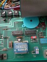
Nothing 'serious' is present in the battery-backed RAM that would cause the device not to function when turned on:

1706874988747.png
I wonder how close this schematic is to your machine: http://matthieu.benoit.free.fr/elan/EA series schematics No 285.pdf?

It may suffice to debug the CPU section.

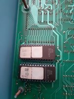
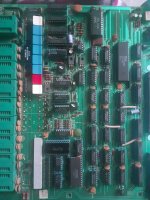
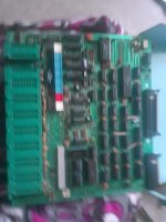
Perhaps post some high-resolution photographs of the main logic board so that we can compare your board with the schematic.

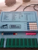
It looks like an ICM7218D is used to drive the seven segment displays. This is an 'autonomous' device and doesn't have a reset pin. As a result, what you could be seeing on the display is the 'random register values' when the programmer powers up. This will also explain why you get largely consistent results, but (occasionally) the odd difference. My starting guess is that the Z80 (or whatever) microprocessor is not starting up correctly and initialising the display driver IC.

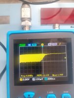
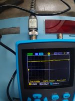
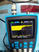
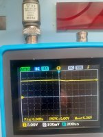
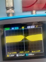
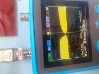
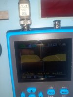
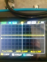
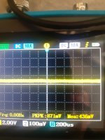
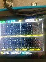
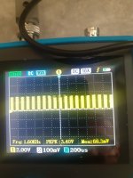
I would check all of the power rails to make sure they are correct, the clock pin and the reset signal. The reset signal appears to be just a CR circuit. If this is the case, the capacitor may have degraded and there is no adequate reset signal to the microprocessor. After that (assuming it is a Z80 microprocessor) I would check the /M1, /MREQ, /IORQ, /RD, /WR and /RFSH pins for any signs of activity.

Dave
 
Last edited:
Thanks to everyone here ,i opened the programmer and took picture of the main board. I took off the 3.6v battery to measure it it has 3.4 v tommorrow will check z80 pins and post the result.
checking the power rails means that i have to check every power regulator on the power supply?
 

Attachments

  • 20240202_175501.jpg
    20240202_175501.jpg
    2.1 MB · Views: 21
  • 20240202_175449.jpg
    20240202_175449.jpg
    1.9 MB · Views: 20
>>> checking the power rails means that i have to check every power regulator on the power supply?

Correct.

Dave
 
Ok after checking the power rails results are
7805 in 9.22 out 4.77
7812 in 32.47 out 11.83
7805 in 95 150 122 and the voltage goes up on and on out 085.1
7805 in 9.22 out 4.87
Z80 pins
M1 1.62v
MREQ 0.53
IORQ 3.10
RD 2.47
WR 4.89
RFSH 1.71
 
I am not sure what you mean by the voltages associated with the second 7805 above. We can't have 95 Volts going in... This would blow the 7805 regulator to bits!

The readings on the Z80 pins imply it is running some program.

I assume you measured these with a multimeter? Do you have any other test equipment at all?

Dave
 
Excuse my ignrance im not an electronic expert , i ve used a multimeter to check voltages,
Also I ve an ocsilloscope .
 
I ve rechecked the ic4 7805 regulator it has 0v on the input and output pin.
The 7805 Its connected to q8 tip32 which has also 0v on the middle pin and 9.47v on both emitter and collector.the q8 tip32 connected to capacitor 3 which i checked it has 9.47v. Resistor 22 has 9.47 both sides.
what component could cause the problem?
 
Sorry the tip32 q8 middle pin is the collector 0v
Base and emitter 9.47v.
 
I ve rechecked the ic4 7805 regulator it has 0v on the input and output pin.
It's pretty likely that anywhere a 7805 regulator is used, the design intended to have at least 7 V (usually a bit higher) on the input pin and 5 V on the output pin. It's further likely that without 5 V sourced from the regulator output pin, a lot of stuff on the board won't work.

I'd start by working backwards from the 7805 input pin to figure out why it's not getting the power supply voltage it needs to regulate. The first thing to check is that the input pin is not shorted to ground.
 
Be careful, this 7805 voltage regulator is a SWITCHED supply. Check the schematic I linked to.

Q8 switches the input supply to the 7805, so what you are reading looks normal, until something decides to switch this 5V supply on.

If you have an oscilloscope that is excellent. Please use that to look at the signals.

Dave
 
No pin of 7805 is connected to ground i ve used my multimeter continuty beeper .
Please were can i check signals using scope from the z80?
 
Im suspecting the tip32 transistor which is doing troubles.i dont have in spare tip32 i have c3117 its pnp bipolar, also i have c3964.could you confirm if it going to be a replacement or not.
 

Attachments

  • 17070461774745714915945066475287.jpg
    17070461774745714915945066475287.jpg
    1.7 MB · Views: 3
>>> Please were can i check signals using scope from the z80?

On the pins of the Z80 I specified in post #4.

Please check the schematic!

There is NO pin of the 7805 (IC4) that is connected to 0V!

Q8 is switched on and off by signal 17 and the voltage of the 7805 is actually controlled by points 15 and 12. I suspect this regulator is responsible for the programming voltage, and requires to be configurable for different device types!

EDIT: Ignore what I said about IC4 being related to the programming voltage, it isn't. This is IC2. However, the points 17, 15 and 12 still controls IC4.

EDIT2: IC4 feeds the VCC supply to the devices being programmed. This will only be present when performing an action on a device (e.g. program, verify, read). As a result, it is not relevant to getting the machine to initially run. I suspect it is digitally adjustable to verify the devices at +5V plus or minus a tolerance.

After checking the various pins of the Z80, check IC7 pins 4, 5, 6 and 7 and IC8 pin 22. Let's see what RAM and ROM the Z80 is accessing...

Dave
 
Last edited:
I tested z80 pins that you ve asked.
 

Attachments

  • 20240204_151404.jpg
    20240204_151404.jpg
    1.3 MB · Views: 7
  • 20240204_151520.jpg
    20240204_151520.jpg
    554 KB · Views: 8
  • 20240204_151645.jpg
    20240204_151645.jpg
    568.4 KB · Views: 8
  • 20240204_151801.jpg
    20240204_151801.jpg
    1.3 MB · Views: 7
  • 20240204_151847.jpg
    20240204_151847.jpg
    1.4 MB · Views: 6
  • 20240204_151400.jpg
    20240204_151400.jpg
    1.2 MB · Views: 5
  • 20240204_151127.jpg
    20240204_151127.jpg
    3.5 MB · Views: 5
  • 20240204_151112.jpg
    20240204_151112.jpg
    1.6 MB · Views: 6
I am afraid none of those signals on the Z80 look any good. Possibly not because of the Z80 though. What actual oscilloscope is it (so I can download the manual)?

IC8 (and IC9) are the two EPROMs on the 'back' ofvtge board.

IC7 is a 74LS139 IC. Let me see if I can find a layout of the PCB. Aren't the part numbers (e.g. IC7) marked onbthe PCB silk screen?

I see from your photographs that the ICs are identified as Uxxx. Can you find U7? This should be an SN74LS139 device.

Dave
 
Last edited:
I tested nec d446c chip pin 4,5,6,7.
 

Attachments

  • 20240204_161442.jpg
    20240204_161442.jpg
    1.4 MB · Views: 4
  • 20240204_161434.jpg
    20240204_161434.jpg
    1.5 MB · Views: 4
  • 20240204_161425.jpg
    20240204_161425.jpg
    1.4 MB · Views: 4
  • 20240204_161417.jpg
    20240204_161417.jpg
    1.4 MB · Views: 4
Back
Top