• Please review our updated Terms and Rules here
  • From now on we will require that a prefix is set for any items in the sales area. We have created regions and locations for this. We also require that you select a delivery option before posting your listing. This will hopefully help us streamline the things that get listed for sales here and help local people better advertise their items, especially for local only sales. New sales rules are also coming, so stay tuned.

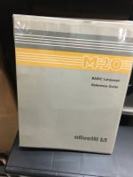
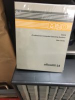
California Olivetti M20 manuals (PCOS and BASIC): Free (you pay shipping)

Covers: California

daverand

Experienced Member
Joined
Apr 25, 2022
Messages
129
Delivery Options
International Shipping or Local Pickup
I have one set of two M20 manuals. These are essentially new - they have been leafed through (in the 1980's) and left in a box since that time. Free to a good home. Local (San Jose) pickup is fine, else shipping cost by the method of your choice.
 

Attachments

  • IMG_2565.JPG
    IMG_2565.JPG
    654.3 KB · Views: 19
  • IMG_2564.JPG
    IMG_2564.JPG
    672.9 KB · Views: 18
Declaring interest and happy to pay the shipping (Oregon). Obtaining an Olivetti M20 is on my wish list. I'll defer to anyone who already owns one, of course.

I've recently become a Z8000 enthusiast...
 
@daver2 has one, but the shipping is stupidly expensive to the UK (~$94). Shipping to oregon will be about $21.50 via priority mail. Can you two work it out, and let me know what you decide?
 
Clearly the answer is for daver2 to ship me his M20. It couldn't be much worse than the Miniframe I recently had shipped to me from Egypt... :)

Anyhow, I will leave the choice to you, @daver2, on whether you want to take them for the shipping. Otherwise, I'm happy to take them at $21.50.
 
That's fine - you take them. Save on my carbon footprint...

>>> Clearly the answer is for daver2 to ship me his M20.

Keep looking, you'll find one - but it may take time...

Dave
 
Ok, please drop me a PM with your address, and I'll get it out to you!
 
Declaring interest and happy to pay the shipping (Oregon). Obtaining an Olivetti M20 is on my wish list. I'll defer to anyone who already owns one, of course.

I've recently become a Z8000 enthusiast...
Hi Scott,
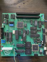
If you are ok with a clone, I made one…🤣

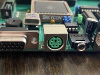
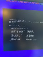
It’s an atx motherboard with vga output, ps/2 keyboard and ide interface. I connected 360 and 640k floppy drives and goteks.

It has a few enhancements, like audio output and RTC. It also has BW and 4 color modes. (I am working on an 8 color version).

Works perfectly with pcos and CPM 8k, although I had to make a couple of patches to the bios to support the IDE drives.

—Salvatore Paxia
 

Attachments

  • 3633C5A9-5755-4ED2-BF95-5F6C7925F177.jpeg
    3633C5A9-5755-4ED2-BF95-5F6C7925F177.jpeg
    2.8 MB · Views: 50
  • 1203BAE7-66C7-4375-8EAA-CD3D648499DF.jpeg
    1203BAE7-66C7-4375-8EAA-CD3D648499DF.jpeg
    2.3 MB · Views: 46
  • E422038A-4284-434F-AF98-6F0F7D8EE5AF.jpeg
    E422038A-4284-434F-AF98-6F0F7D8EE5AF.jpeg
    1.9 MB · Views: 46
Last edited:
Absolutely! I want to make one!! Where can I learn more? Are pcboards for sale and/or are the gerbers available?

This is very exciting!

Scott
I’ll put it on GitHub when I am done. Unfortunately I made a couple of errors on the pcb. The worst is a wrong atx power supply pinout, so I use a patched atx cable extender.

I am also working on the the 8 color version and on an ide controller which doesn’t require any bios changes because my original goal was to use an unmodified bios.

I think you had a similar issue in one of your projects because of the difference in sector number between WD1000 and IDE.

Then the last two things that I want to add are
1) compatibility of the two expansion slots with the APB8086 board (currently it won’t work).
2) 8mhz turbo mode. This kind of works but I suspect that I will need to patch some bios timings to be perfect.

Some changes will be bios or pld, but since the pcbs are large, i don’t want to rush a second version.

Meanwhile, if you don’t mind having to deal with the patched atx connector I can send you a pcb and add you to my private repository. Just PM me. It will be fun to have somebody else hacking it.
A friend of mine also made one. If you don’t care about the 8 color mode it works really well.

A warning though: it needs a ton of hard to find parts (8251,8253,8255,8259,fd2797) although i can probably disable some checks in the bios to avoid mounting the 8255 and the floppy controller.
 
I'll send you a PM.

It was the QX-10 where I had to deal with sector translation, disassembled the BIOS in a few places and did some manual patching. Would love to find a way around the issue and not require patching. Interested to hear what your ideas are.

Finding obsolete logic is something I'm used to. I'm pretty sure I have everything on that list except perhaps the 8251.

Scott
 
I’ll put it on GitHub when I am done. Unfortunately I made a couple of errors on the pcb. The worst is a wrong atx power supply pinout, so I use a patched atx cable extender
A warning though: it needs a ton of hard to find parts (8251,8253,8255,8259,fd2797) although i can probably disable some checks in the bios to avoid mounting the 8255 and the floppy controller.
I would also like to queue up for a revised PCB, eventually with selectable color support, so I do not need to set the jumpers to switch between b/w and colors
 
I would also like to queue up for a revised PCB, eventually with selectable color support, so I do not need to set the jumpers to switch between b/w and colors
Sure. But what do you mean with selectable color support? Something like a bios configuration utility?
 
yes. remove the COL/BW jumpers would be nice. The RTC may be able to store the configuration. How to replace the jumpers in HW, that I haven't thought about.
In the RTC eeprom I wanted to store which portion of a larger hard drive to use, to have multiple logical hard drives (until someone manages to change PCOS to support more drives and larger ones).
Since I made an IDE controller & RTC clock board for the original M20, I think it was the correct place to store it.

I can actually store the hardware configuration in the ATMEGA 164 eeprom. I have a bunch of BIOS patches that I apply to the olivetti bios to support certain devices (IDE, RTC, sound, etc).
When I have some time, I'll change the ATMEGA firmware to patch the bios on the fly, so one could upload (via serial) the original bios and a list of patches and then decide which patch to apply
through a menu. From the atmega serial port it would be trivial to control. From the M20 bootloader it would be a little bit trickier but not impossible, since the ATMEGA has full control of the boot process.
I am going to implement this to disable the chip selects for my I/O devices (IDE, Sound and RTC).

One way to implement it would be to read the hardware configuration from the ATMEGA EEPROM and inject some Z8001 code which then writes it to latches in the PLDs before giving control to the M20 bios.
The bios would be unchanged. I hope this is clear enough...

The problem is that I ran out of I/O pins in the PLDs. I am using ALL of them. I even had to add a 3 to 8 decoder for some chip selects to free a couple of pins.
While the configuration is read from a port (port 0x21), and that could be maintained without the DIP switches, the BW and 4/8 color signals are needed in the VGA controller PLD to process the color planes
properly. Currently these signals are fed directly to the VGA controller from the dip switch.

Hence the feature you are asking would be hard to implement with the current PLDs. I managed to implement the 8 color mode with a larger PLD with exactly 100% of the PLD blocks.
So it's currently not possible to add additional features that require more PLD resources, especially the VGA controller. The floppy drive selection (160,320,640) on the other end, could definitely be done.

One could always use larger PLDs or a single FPGA, but then it would become harder to keep the board through hole and 5V.

Sorry, this is kind of off-topic here!
 
I'm curious as to how you'd make the 8 color work? The M20 uses 3 memory cards with shift registers. If you only have one memory chip, how does one read 3 memory locations at the same time to load the 3 shift registers?
Maybe, I don't understand how the shift registers are loaded and it reads them in sequence and not all at the same time?
Dwight
 
I'm curious as to how you'd make the 8 color work? The M20 uses 3 memory cards with shift registers. If you only have one memory chip, how does one read 3 memory locations at the same time to load the 3 shift registers?
Hi Dwight.
Since I am using a DPRAM (and quite fast), while the shift registers (3x16 deep) are shifting pixels out I am latching the next 3 color planes in. I forget the exact timing but it’s roughly every 5 horizontal shifts. I might have used a slightly uneven scheme for an easier select but it’s still within the memory access time.
At the end of the shifting I load the 3 locations from the latches into the shift registers.
It uses quite a few PLD blocks but it’s quite easy to implement.
One optimization I did is that the first color plane is loaded directly into the shift register and not into latches first.

The outputs of the 3 shift registers are then selected or mapped with the 4 color LUT according to the color mode. The LUT is also inside the VGA PLD.

Unfortunately the larger PLD needed for the 8 colors has the same pinout but 3 I/o pins are missing! Didn’t realize it until i synthesized the 8 color design…

So now I have to move something out to TTL Logic (some simple clock dividers for the LSI chips) to free up the 3 pins.
It will then be compatible with all the screen modes and both small and large PLDs.
 
Last edited:
It sounds like you have it under control. I didn't think about the fact that the reads of the RAM were actually quite spread in time ( multiple pixel times ). Decoding the 8 colors into additional I/Os must have been a pain. I only have one black and white display to worry about.
Dwight
 
It sounds like you have it under control. I didn't think about the fact that the reads of the RAM were actually quite spread in time ( multiple pixel times ). Decoding the 8 colors into additional I/Os must have been a pain. I only have one black and white display to worry about.
Dwight
Exactly! The color output itself is not a big deal since I am using a vga output with just two levels: for bw I just copy the color plane to all the RGB outputs. For 4 colors, 2 bit planes go into the LUT then RGB. For 8 colors each of the 3 color planes goes to a color…
 
Back
Top