SomeGuy
Veteran Member
As I have mentioned before, I have several Samsung SyncMaster 753DF VGA CRTs that have developed various problems. One has a CRT with too much burn in to be really usable and the other has lost all control of the horizontal width, displaying too wide and warped.
I also have a SyncMaster 755DF that seems to have developed an intermittent loose connection on one of the color signals somewhere.
In my opinion, these were some of the best VGA CRT monitors out there. Much clearer than any of the other non-trinitrons, while not as hard on my eyes as the trinitrons.
The shells on these monitors do not just unscrew. They are designed to keep untrained personnel out.
There is a service manual floating around that describes how to open the case and remove the boards. But doing so requires a special "opening jig", which they do not clearly show in the photos. Some of the terminology is not not very clear. It also requires some desoldering.
So I will try to document my attempt at opening and disassembling one of these monitors.
Anyone trying to dissemble one themselves should refer to the manual. My notes are not a how-to, they are just to answer questions I had, and hopefully might help others. I am also assuming previous knowlede of working with CRT monitors.
Yada, yada, yada, zap. You did unplug it first, right?
Removing the outer shell:
There are four plastic "hold-snaps" that must be undone.
You will see two small rectangular holes on the top of the monitor shell. Two of these hold-snaps are underneath.
You will see two sets of squeezable clips (the manual confusingly also call these hold-snaps) at the back bottom. The other two hold-snaps are immediately underneath these clips.
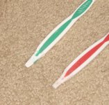
From what little I can tell in the photos, and from working on these units, the "opening jig" is a small thin metal tool with rounded edges, and a grove guide at at least one end. You could probably just use a screw driver for the top hold-snaps, but not knowing what to expect inside, I sanded down a pair of toothbrushes to a similar shape to avoid scratching anything.
The instructions show undoing one at a time starting at the top. But for me it seemed easier to start with the bottom, and then undo the top two, at the same time so they don't lock back down.
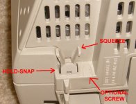
The bottom hold snaps are kind of weird. On each you have to squeeze the pair of clips above the snap, which allows the snap to move up. Then you are somehow supposed insert the magic Opening Jig in to the groove on the bottom of the hold-snap.
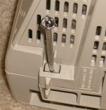
What worked for me was inserting a tiny flathead screwdriver under each snap. Instead of undoing one at a time, I just left the screw drivers there while undoing the two at the top.
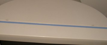
Next, I inserted my home-made flat plastic tools in to each of the holes on the top. Pushing them in, each side made a "click" sound indicating that the hold-snap was disengaged.
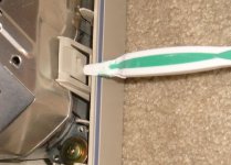
This is what is underneath.
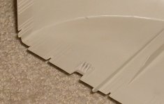
This is what is on the inside of the shell.
The manual states this, but it is important to note again - do not try to pry the shell open.
Removing the back of the shell requires quite a bit of pulling. I was afraid a snap was not undone or something was going to break, but it did come off eventually.
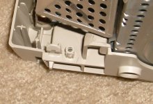
This is what the lower snap looks like after opening.
Note that if the lower hold saps break, there is a small indentation next to them on the outer shell where a screw theoretically can be installed. Notice how the above photo shows a screw mount inside.
Anode:
With the back off, the next step is to careful discharge and undo the CRT anode. A grounded metal tool should release any charge, obviously avoid touching the metal anode lead.
CRT PCB:
Now you want to remove the PCB attached to the back of the tube. The socket is secured on to the tube by some plastic grips secured by a metal ring.
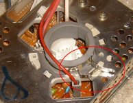
This ring has a little lever on it that you can easily pull up to loosen it. The manual calls this the "Video Spring", and the photo is clear as mud.
Annoyingly, little plastic grips snugly attached on the back of a hot tube for 20 years are going to be as brittle as eggshells. They will likely break or already be broken.
The manual says to start desoldering the CRT PCB shield, but it would make more sense to unsolder stuff from the CRT PCB AFTER the main PCB is removed. The CRT PCB shield is indeed soldered on to the PCB, preventing easy removal. For what I am doing, I don't believe I need to remove that anyway.
I'm not separating the CRT PCB from the the main PCV, so I only have to disconnect plugs between the yolk, degaussing coil, and various grounding wires to prepare to remove the main PCB.
Main PCB:
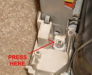
Finally there are two "hold-clips" on each side of the main PCB that hold it in. I'm still not sure how exactly one would use their "opening jig" on it. The bottom part of this hold-clip has a groove in it, but you can't push anything through the mounting hole, and not much to use as a lever. I was afraid a metal screwdriver might break them.
But, just pushing the bottom (grooved side) of each hold-clip with my home-made plastic tool unlatched it without much difficulty.
From here on out, it is pretty much the same as any other CRT monitor.
What I was wanting to do was try and swap the boards between CRTs as the one with screen burn in obviously has good boards. Unfortunately, these boards are slightly different revisions. Among other things they have different degassing plugs on the main PCB.
When I tried the good board on the one with the deflection problem, it only gave me a very vague scrambled picture. So it might not be compatible with the yolk or CRT. Might fiddle with it a little more later.
I also have a SyncMaster 755DF that seems to have developed an intermittent loose connection on one of the color signals somewhere.
In my opinion, these were some of the best VGA CRT monitors out there. Much clearer than any of the other non-trinitrons, while not as hard on my eyes as the trinitrons.
The shells on these monitors do not just unscrew. They are designed to keep untrained personnel out.
There is a service manual floating around that describes how to open the case and remove the boards. But doing so requires a special "opening jig", which they do not clearly show in the photos. Some of the terminology is not not very clear. It also requires some desoldering.
So I will try to document my attempt at opening and disassembling one of these monitors.
Anyone trying to dissemble one themselves should refer to the manual. My notes are not a how-to, they are just to answer questions I had, and hopefully might help others. I am also assuming previous knowlede of working with CRT monitors.
Yada, yada, yada, zap. You did unplug it first, right?
Removing the outer shell:
There are four plastic "hold-snaps" that must be undone.
You will see two small rectangular holes on the top of the monitor shell. Two of these hold-snaps are underneath.
You will see two sets of squeezable clips (the manual confusingly also call these hold-snaps) at the back bottom. The other two hold-snaps are immediately underneath these clips.

From what little I can tell in the photos, and from working on these units, the "opening jig" is a small thin metal tool with rounded edges, and a grove guide at at least one end. You could probably just use a screw driver for the top hold-snaps, but not knowing what to expect inside, I sanded down a pair of toothbrushes to a similar shape to avoid scratching anything.
The instructions show undoing one at a time starting at the top. But for me it seemed easier to start with the bottom, and then undo the top two, at the same time so they don't lock back down.

The bottom hold snaps are kind of weird. On each you have to squeeze the pair of clips above the snap, which allows the snap to move up. Then you are somehow supposed insert the magic Opening Jig in to the groove on the bottom of the hold-snap.

What worked for me was inserting a tiny flathead screwdriver under each snap. Instead of undoing one at a time, I just left the screw drivers there while undoing the two at the top.

Next, I inserted my home-made flat plastic tools in to each of the holes on the top. Pushing them in, each side made a "click" sound indicating that the hold-snap was disengaged.

This is what is underneath.

This is what is on the inside of the shell.
The manual states this, but it is important to note again - do not try to pry the shell open.
Removing the back of the shell requires quite a bit of pulling. I was afraid a snap was not undone or something was going to break, but it did come off eventually.

This is what the lower snap looks like after opening.
Note that if the lower hold saps break, there is a small indentation next to them on the outer shell where a screw theoretically can be installed. Notice how the above photo shows a screw mount inside.
Anode:
With the back off, the next step is to careful discharge and undo the CRT anode. A grounded metal tool should release any charge, obviously avoid touching the metal anode lead.
CRT PCB:
Now you want to remove the PCB attached to the back of the tube. The socket is secured on to the tube by some plastic grips secured by a metal ring.

This ring has a little lever on it that you can easily pull up to loosen it. The manual calls this the "Video Spring", and the photo is clear as mud.
Annoyingly, little plastic grips snugly attached on the back of a hot tube for 20 years are going to be as brittle as eggshells. They will likely break or already be broken.
The manual says to start desoldering the CRT PCB shield, but it would make more sense to unsolder stuff from the CRT PCB AFTER the main PCB is removed. The CRT PCB shield is indeed soldered on to the PCB, preventing easy removal. For what I am doing, I don't believe I need to remove that anyway.
I'm not separating the CRT PCB from the the main PCV, so I only have to disconnect plugs between the yolk, degaussing coil, and various grounding wires to prepare to remove the main PCB.
Main PCB:

Finally there are two "hold-clips" on each side of the main PCB that hold it in. I'm still not sure how exactly one would use their "opening jig" on it. The bottom part of this hold-clip has a groove in it, but you can't push anything through the mounting hole, and not much to use as a lever. I was afraid a metal screwdriver might break them.
But, just pushing the bottom (grooved side) of each hold-clip with my home-made plastic tool unlatched it without much difficulty.
From here on out, it is pretty much the same as any other CRT monitor.
What I was wanting to do was try and swap the boards between CRTs as the one with screen burn in obviously has good boards. Unfortunately, these boards are slightly different revisions. Among other things they have different degassing plugs on the main PCB.
When I tried the good board on the one with the deflection problem, it only gave me a very vague scrambled picture. So it might not be compatible with the yolk or CRT. Might fiddle with it a little more later.
