falter
Veteran Member
I'm going to create a thread here to separate my repair efforts with both this TV Typewriter and my Mark-8. As always assistance is deeply appreciated. I recognize I am just a temporary caretaker, so I want to see these things go on to their future homes better than I got them.
I'm not looking to fix this overnight but just sort of getting organized and figuring out what I can do to safely test things.
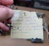
As we know the label on the front of the case says built by Grant Runyan 1976. I'm not sure if that refers to the actual TVT itself or the box. I see evidence that this TVT may have been built to the basic spec earlier than 1976.. I haven't found a single chip so far that is later than 1974. The keyboard is a first generation SWTPC KBD1, which was designed by Don himself.
I see the remnants of the twinlead that would have been for TV use - it looks like it was clipped at one end. I suspect if it had never been used it would never have been installed, so that's why I kind of think this TVT arrived where it is in stages. There are two 'bonus' boards - one is Roger Smith's serial comm board, which I understand the hobbyist could etch themselves or order from techniques. I believe this board is the latter since it has professional quality silkscreening. There is another board composed mainly of 7400s and 7474s that seems to be inline with the video out. Not really sure what that does.. maybe enhanced cursor control or more function keys?
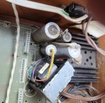
I guess the first place to start would be the 'mainframe' or motherboard, which is where power comes in. The power cable is chewed or has been rubbed in a way that the copper is exposed. I think I can save it as it's quite long so I'll just cut the bad bits off and resolder.
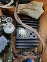
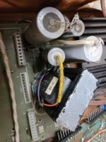
The PSU seems to mostly conform to the original design - it has a Signal 24-1A transformer. However, it looks like Grant deviated a bit - there is a 309 regulator with big heatsink installed - no 7805. Inside the box on the back wall is a warning not to power up the mainframe without other boards plugged in, otherwise it could damage the zeners. I don't know if that is applicable with this mod in place.
Also, the motherboard is missing one molex connector for the bus. I am not sure if this is on purpose or not.. I see a molex connector stuck to the underside of one board.
I do not have a variac.. but I'm willing to get one.. just have to understand how to hook it up properly.
I'm not looking to fix this overnight but just sort of getting organized and figuring out what I can do to safely test things.
As we know the label on the front of the case says built by Grant Runyan 1976. I'm not sure if that refers to the actual TVT itself or the box. I see evidence that this TVT may have been built to the basic spec earlier than 1976.. I haven't found a single chip so far that is later than 1974. The keyboard is a first generation SWTPC KBD1, which was designed by Don himself.
I see the remnants of the twinlead that would have been for TV use - it looks like it was clipped at one end. I suspect if it had never been used it would never have been installed, so that's why I kind of think this TVT arrived where it is in stages. There are two 'bonus' boards - one is Roger Smith's serial comm board, which I understand the hobbyist could etch themselves or order from techniques. I believe this board is the latter since it has professional quality silkscreening. There is another board composed mainly of 7400s and 7474s that seems to be inline with the video out. Not really sure what that does.. maybe enhanced cursor control or more function keys?
I guess the first place to start would be the 'mainframe' or motherboard, which is where power comes in. The power cable is chewed or has been rubbed in a way that the copper is exposed. I think I can save it as it's quite long so I'll just cut the bad bits off and resolder.
The PSU seems to mostly conform to the original design - it has a Signal 24-1A transformer. However, it looks like Grant deviated a bit - there is a 309 regulator with big heatsink installed - no 7805. Inside the box on the back wall is a warning not to power up the mainframe without other boards plugged in, otherwise it could damage the zeners. I don't know if that is applicable with this mod in place.
Also, the motherboard is missing one molex connector for the bus. I am not sure if this is on purpose or not.. I see a molex connector stuck to the underside of one board.
I do not have a variac.. but I'm willing to get one.. just have to understand how to hook it up properly.
")