neosunrise
Experienced Member
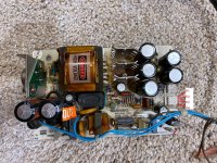
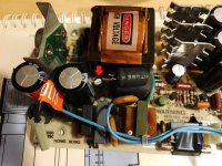
I recently obtained an Osborne 1 (I believe it is the later version as it does not have the Osborne 1 banner on the side of the case. Anyway, it's dead and I found that the Astec AC8151 power supply will not provide correct output. I measured the output pins, and here are the results: P1: -3.8V (supposed to be -12V), P2: +5.6V (supposed to be +12V), P3: Common, P4: +2.58V (supposed to be +5V). Please see attached picture for the pin arrangement (I already replaced the three RIFA capacitors that had lots of cracks). It seems that all outputs were significantly lower than the correct numbers.

I followed the Astec AC8151 Power Supply Repair Manual and checked the components. It seems that the thermister R1 and the diode bridge DB1 both were okay. The power transistor Q2, I desoldered it, and used my multimeter to measure the resistance between the base and collector, one way measured 12ohms, and they other way measured infinity. It showed similar results when measuring the base and emitter. The resistance between emitter and collector was infinity. I guess this is okay? I followed all steps in Section III, and all looked okay before step E. I have not got a chance to check the waveforms but I was wondering if there's already something wrong that you guys found? The circuit board below the three rectifier assemblies seems cooked, but I can't seem to easily desolder these assemblies to test. Is it possible that they are dead? Or could it be something else, considering that there is output, just low?

I followed the Astec AC8151 Power Supply Repair Manual and checked the components. It seems that the thermister R1 and the diode bridge DB1 both were okay. The power transistor Q2, I desoldered it, and used my multimeter to measure the resistance between the base and collector, one way measured 12ohms, and they other way measured infinity. It showed similar results when measuring the base and emitter. The resistance between emitter and collector was infinity. I guess this is okay? I followed all steps in Section III, and all looked okay before step E. I have not got a chance to check the waveforms but I was wondering if there's already something wrong that you guys found? The circuit board below the three rectifier assemblies seems cooked, but I can't seem to easily desolder these assemblies to test. Is it possible that they are dead? Or could it be something else, considering that there is output, just low?
Last edited:


