• Please review our updated Terms and Rules here

Osborne 1 Video Adapter.

I don't have my CNC set up at the moment, but have to make some new PCBs in the next month for a customer, so when I do I'll CNC up some extra PCBs of this and let's see if we can work out how to ship these to the US as a letter so I can figure the cost of shipping a single PCB by itself.

Theoretically, I should be able to send it so you can just solder it up and pop it out of the holder... After all, that's how I made them. I'll print up the extra spacers for the edge connector also so you don't have to judge and solder carefully.

But give me a little while since I'm not sure when I'll get around to the PCB making part of the project.

It won't be tinned, but it should solder up OK. And IIRC, your soldering skills are pretty good.
 
PCB File in FreePCB format, and Gerbers.

Also, some notes I earlier communicated in a PM that may assist anyone.

Three things to be certain of during assembly.
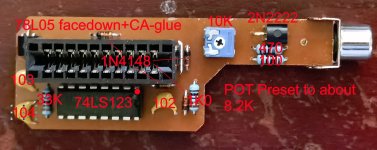
1) Glue the 78L05 down to the PCB to help distribute heat. There's no room for a heatsink. though it is possible to include a thin piece of heatsink metal bent if necessary.
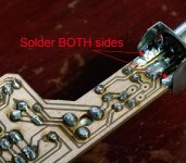
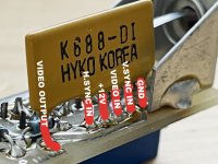
2) The Video Connector bridges both sides of the PCB and carries ground to the final output transistor section. So if you connect wires, don't forget to bridge the grounds with a piece of wire since there's no jumper there.
3) The edge connector is spaced from the PCB by about 2mm. I do have a 3D printer spacer, but this can also be done when soldering.

I used these connectors for the RCA connector: https://www.aliexpress.com/item/4001050402165.html
And these for the edge connector: https://www.aliexpress.com/item/1005003003362076.html - eg, 20 pin version.

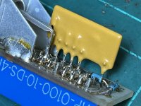
Also, none of the components can be higher than the chip when soldered fully in. There is not much space under the PCB, so capacitors are on their side and all components are flat, including transistors. Flat face down. There is no room for sockets and capacitors and transistors should be on their flat side. Diodes are all 1N4148 or similar small signal diodes. They are used mostly to adjust the voltage levels of the output signal by the same amount as the bias voltage.

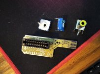
I used potentiometers like this;
https://www.aliexpress.com/item/1005002780073685.html

I didn't use that specific one, but it's probably the same size. It can be adjusted from the PCB side, to make tuning easier as each unit must be appropriately adjusted, though the values are relatively consistent to set them in advance.

Regards
David
 

Attachments

  • drill_file.zip
    4.4 KB · Views: 3
  • OsborneShunt mk3 v8.zip
    5.7 KB · Views: 4
Back
Top