• Please review our updated Terms and Rules here

Osi c4p

For an experiment, I pulled out the 8T26 at U3H, and I bent out pins 12 and 14. Then I plugged back in and fired up. Now there is signal on pin 14. Nothing at all on pin 12 (neither high nor low, which makes sense since it is tied to and thus driven by pin 14?). I'm just reading up on the 8T26 but it seems like the problem must be towards that 175 somewhere.
 
Got it!!

So basically I followed the trace from U4G pin 13. It's hard to explain, but essentially if you think of three vias arranged as points of a triangle, the trace coming from pin 13 attaches to the bottom left point, and then the trace runs under on the other side to the bottom right point, coming back up and running a short distance under U4H before going under again through another via, and a straight shot to pin 3 of J4I (the keyboard connector).

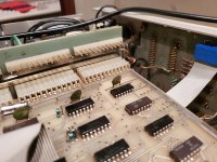
On close inspection, I realized the metal cap that runs over all three 'points' of the triangle was really close, maybe even touching. I also found what appeared to be corrosion or maybe old solder flux (the previous owner didn't do a great cleaning job on that). Anyway, it appeared to have 'metastasized' to the point that it may have been making contact with either the metal body of the cap, or the top point of the triangle (which is not supposed to be connected to the other two points), or both. Anyway, I moved the cap as much as I could upwards, scraped away the residue, and immediately I had everything working properly!

Dave you were invaluable as always. I think I was mostly on the trail... I just wasn't confident that KD2 necessarily had to be having some kind of activity on it.

Anyway, now I'm going to try, without breaking anything else, to put it all back together and play with it a bit. I'm curious to see an OSI with colour!

And then I can pack this away for a bit while I await the tapes, and try to get this adapter for the Microkit finished so we can see what the rest of the 1702 data is.
 
One thing I *am* curious about - I was really hoping to use my other, empty C4P case to plug my plain jane 500 and 440 boards into.. however I discovered that the -9V line is not connected to anything. I had wrongly assumed OSIs were always rigged up with +5, +12 and -9V. I guess not. I'm not sure how I'll deal with that, or if I will, but in the meantime I was looking the backplane of the 'full' C4P I've been working on, and I did find this large resistor attached to the -9V line. I'm not sure what that is supposed to do.. looks like it goes to pin 25 of one of the DB25 ports. Looks like there is another wire attached there too that was cut. I'm wondering if he was feeing in something slightly higher than -9V and the resistor cuts it down? Or maybe just using the -9V rail/pin for something else entirely.

20191229_122446.jpg
 
Okay, one more potential problem.

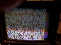
So far everything operates just fine, however I decided to try out the color mode. You invoke color mode by using a POKE statement, in this case, POKE 56832,5 (64 columns, no sound). However, when I do that, I get this:

20191229_205710.jpg

Doesn't photograph very well, but you get the idea. It throws up color blocks all over. I'm assuming this is a bug, not a feature. I'm pretty sure the color video RAM is good.. it was among the RAM I tested in the Hazeltine. Not really sure on this one. :) First time I've ever seen any kind of color out of an OSI product. :)
 
Try writing a program to preset all the colour ram to a certain value. If it works, then the ram is ok.

I had a computer where the colour was an extra part, and you had to initialise the ram yourself.
 
Hi Falter, Robbbert, et al.

Try this and let us know what you get:

#SHOW ALL CHARACTERS
10 FOR T = 0 TO 255
20 POKE 57344+T,T
30 NEXT
40 FOR T = 0 TO 255
50 poke 53248+T,T
60 NEXT
RUN

# TURN COLOUR ON
POKE 56832,4

Should look something like:
C4Pa.jpg

Cheers,
Red
 
Good work that man!

Conductive flux/corrosion etc. once again. Always a good place to start with a bright light, magnifying glass and some flux cleaner.

I agree with the previous post. The colour information will require additional RAM. Either that RAM could be faulty or, as explained, it may contain garbage. If it is not initialised prior to entering colour mode, you may get random foreground and background colours. With a lot of [SPACE] characters on the screen by default, you will get random blocks of background colours (exactly what you see)...

Dave
 
Hi Falter, Robbbert, et al.

Try this and let us know what you get:

#SHOW ALL CHARACTERS
10 FOR T = 0 TO 255
20 POKE 57344+T,T
30 NEXT
40 FOR T = 0 TO 255
50 poke 53248+T,T
60 NEXT
RUN

# TURN COLOUR ON
POKE 56832,4

Should look something like:
View attachment 58347

Cheers,
Red

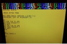
Hmm.. nope.. I get this:

20191230_101008.jpg

I can see it drawing out all the characters when I run the program, although they disappear above the visible range of the screen. But as soon as I run the color invocation, it does as you see there.
 
So there is something not right here somewhere...

Graphic mode is described here on page 27 http://www.osiweb.org/manuals/c4man.pdf.

Character memory starts at 53248 whilst colour memory starts at 57344.

Poke 56832,4 should set 32 column mode, no sound and enable colour. I see your screen is in 32 column mode, but Red’s screen appears to be in 64 column mode still.

When your machine starts up, is it in 32 or 64 column mode and how many lines of text are there by default? Just type random garbage to find out! I see very early on that it was in 64 column mode.

Let’s make sure the machine works in monochrome mode first. Do you get all of the correct characters displayed?

I suspect either colour RAM is not being written to or read from. I have a simple way of checking this later.

By the way, what type of ROMs have you got in this machine, and have you played with the machine code monitor yet?

And welcome to the forum Red! Your posts will be moderated for a few more posts.

Dave
 
According to my manual, POKE 56832,4 *should* be 32 character, sound off, color on, and that's what it seems to do, yes. Not sure what's up with Red's there.

My machine starts up in 64 column mode. I will do a quick test to see how many rows I'm getting. I'm still sort of wondering if the counters could be an issue here - they have occasionally on power up, cut off the first column entirely. I'm still trying to figure out if it's a bad or loose connection somewhere.

The ROMS are 'OSI BASIC 3.2' . The CPU board is a 502.

I just did a 'test' for the number of lines available - I hit Return 27 times before OK prompt disappeared up top. So I'm thinking something is still off with the vertical, maybe a bad counter still in there somewhere. I seem to recall powering up once and having zero until I swapped two of them around. Regrettably, I don't have any more 163s kicking around to swap in.
 
Incidentally, colour is stored as 4 bits only. Red, Green, Blue and ‘colour invert’

You could try the following program:

10 FOR I=0 TO 15
20 POKE 57344,I
30 PRINT PEEK(57344)
40 NEXT I

This program should print out the numbers 0 through 15 indicating that it can both write to (and read from) the first byte of the colour memory. If this doesn’t work, we will need to find out why!

Dave
 
224 (decimal) = E0 (hexadecimal).
239 (decimal) = EF (hexadecimal).

Only the lowest 4 bits are used (the upper 4 bits are ‘rubbish’ and can be ignored).

This looks like you can correctly write to (and read from) the first byte of colour memory.

Let me have another look at the schematic of the video card for the next step.

Dave

I wish I knew what the 'normal' screen is supposed to look like when you just invoke color mode without doing any programming. Just as a note, I swapped the 7404 that is part of the color circuitry (only IC left in that circuit that is socketed).. more of the color blocks turned orange, similar to the screen in the Red's example.
 
My guess is that BASIC should clear the colour RAM out to a sensible default value (whatever that is) on startup (in a similar manner to clearing the screen).

There are a couple of 74175 latches (U1E and U1D) in series that latch the colour information. A fault in one of these could cause problems. Don’t, however, just swap them over, as the same fault (if one is present) will persist!

After that, the RGB outputs are gated through U1C (7400) and then drives U1A (74151).

The colour oscillator (X2 and associated components) feed a 7404 (U1B) that delays and inverts the colour oscillator as the signal propagates through the gates (ugh...). This forms the CDx signals fed into U1A. The RGB signals select which of the 7 colour clock inputs (or black?) are ultimately fed to the video signal forming sub-circuit.

My concern is the gate delays of the 7404 that produces the colour clock. If my hunch is correct (and it may not be) an ageing 7404 will slow down and could affect the colour. Replacing it for a modern (and therefore faster) device could also affect the colour!

I will need to swat up on composite video signals again!!!

Dave
 
Well, we won't be just swapping the 175s as those are soldered. I'll have to see if I have any spares before I break put the desoldering pump. It's interesting that you mention the 7404.. as I mentioned when I swapped it the video background changed. I believe I have a high speed 7404 variant around I could try just as an experiment.. think it was designated high speed IIRC.
 
Another hunch, there are a lot of 74123s around. These (and the associated timing components) age. It would be worth checking the pulse length/ delay with the documented value using an oscilloscope to see if they are close to the identified value.

You could checkout the double latches by filling the entire colour space memory with the same colour (using a BASIC program in a loop) and checking the 4 bits from the output of U1D for correctness.

Dave
 
Back
Top