NeXT
Veteran Member
When you get into the Vintage Computer field there will eventually come a time when you wish you had an EPROM programmer either to dump a ROM image and upload it wherever or to burn a new ROM. When you look around you will notice that it's open season on chip programmers. Some have additional handy features like ICSP or JTAG. Some are the complete deal with a microcontroller and dedicated disk with an LCD interface and cost thousands. Others are a bare board and cost no more than $40 off the boat from China.
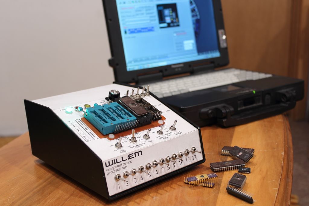
In 2011 my need for a programmer came to a front. I had a Lisa whose SCSI card had no EPROM and same with an Apple II. I knew nobody with a programmer and having just moved to another apartment in Vancouver I wasn't going to gamble $300 on a programmer I might use once or twice. I ended up buying the Willem 5.0e(nhanced)
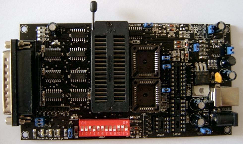
They're the cheapest thing you can get your hands on. The software can be odd at times, support can be fly-by-night and like the RasPi it has no enclosure but it can program just about anything.
After only two days of use though I was starting to itch that it could be improved. You had to pretty much isolate it from any metal surfaces and changing jumpers could be a pain. I wanted the look of the more professional units. After some careful planning I looked at my options and decided while it might end up a complete hack it would work.
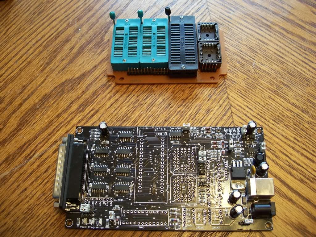
The first thing I did was determine how to place everything. I went to one of the local hobby shops and purchased a nice aluminum and steel box with an inclined front. I then desoldered and removed the chip sockets. Insertion-Force sockets had to go so I replaced them with TEXTOOL sockets. I found I could fit everything nicely onto a separate PCB which I could mount on the top of the box.
>>>IMAGE<<<
>>>IMAGE<<<
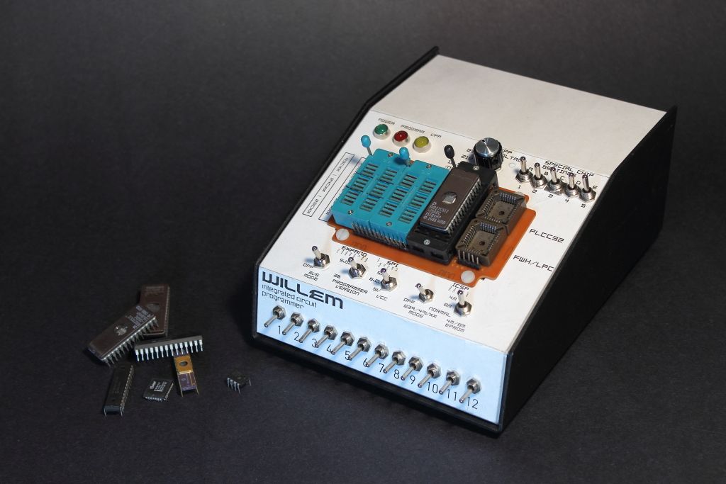
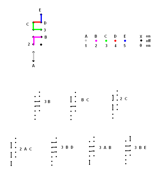
I found that for most of the jumpers I could resort to mini toggle switches. The dip switch bank in particular was going to be fun but those were all easy to order. When you ran into the large configurations that involved two ore more different jumpers at a time you needed to get creative. From the start it made more sense to cannibalize the four position rotary switch from a parallel port switch to set the VPP jumpers. The same was going to be done with the "Special" chip settings however it soon became apparent that it would need something far more complex than anything you would find in a parallel switch. After one or two sleepless nights (did I mention I have anxiety problems?
") ) I clued in that the jumpers were sharing common pins. I was able to replace the rotary switch with five ON/OFF/ON toggle switches.
) I clued in that the jumpers were sharing common pins. I was able to replace the rotary switch with five ON/OFF/ON toggle switches.>>>IMAGE<<<
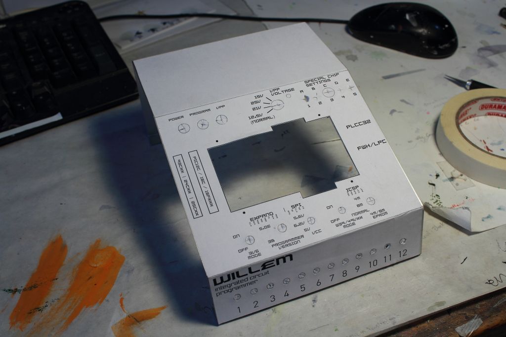
At this point the project stalled for about a year due to moving residences yet again and the lack of a Dremel or drill. By the time I returned to it a month ago I now had a limping Dremel with one blown winding and one of those jigs that converted your Black and Decker drills into a press. I was able to cut out the openings on the front for the chip socket PCB and drill the holes for the LED's and switches while on the back openings were added for the parallel port and for 12V DC to come in because it made absolutely no sense to continue using USB power which wouldn't give me the full range of programming voltages.
This is also the point where I scanned in my rough draft of the switch layout and drafted a more professional looking overlay that was glued on to indicate what everything did. Now that everything had been broken out, there was a lot going on. Once the glue set I was able to begin installing components.
>>>IMG<<<
>>>IMAGE<<<
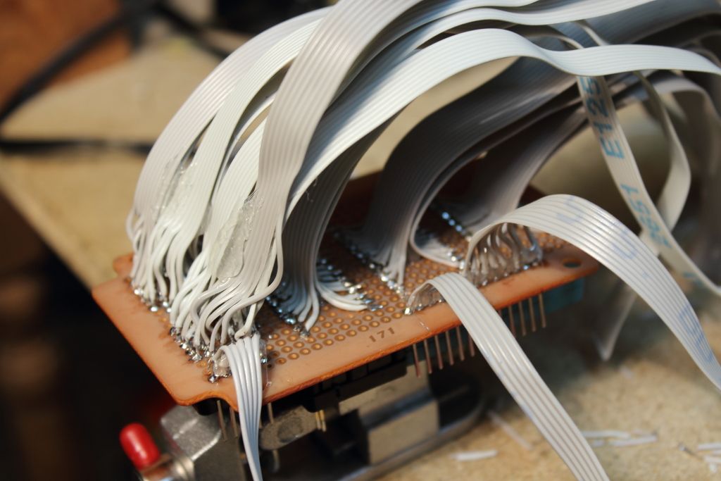
Now came the part I was not looking forward to. Soldering.
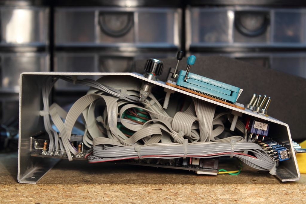
Doing the rough math there was to be close to 200 individual solder joints, half of them to surface mount connections on the backside of the socket PCB. I mulled over how to arrange the wiring and decided the best route would be to remove the socket PCB for now and build the harness using ribbon cable which can be nothing short of a nightmare to strip and solder and I had to use it on EVERYTHING. The final product was most likely going to resemble the Cray 3 Brick.
>>>IMAGE<<<
>>>IMAGE<<<
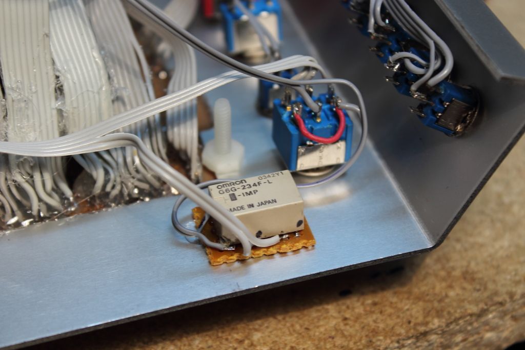
Among that mess there was logical thought that went into the arrangement and it helped considerably as for the next two weeks I was down with a pretty nasty cold and finally came back, barely remembering what I had done. Wanting to finish the programmer before Christmas I made one final push to assemble and test it. The final stages of connecting the wires to the programmer, the switches to the programmer, replacing the boards SMD LED's and installing 300 and 500 ohm resistors to make use of the LED's on the front, cleaning up the cables and organizing the harness took eleven painful hours. In the process I discovered that one of my toggle switches for setting "Normal, 8M and 4M" chips wouldn't work. Three position two pole switches either came in on/off/on or on/on/on 3-way switches. Because the three jumpers it replaced needed to be isolated from eachother I could only choose from two of three settings. After a break I realized that I could set those two modes with one pole and the third with the other using a relay scavenged from a dead hard drive. Wiring to NC, when in the 8M mode the relay remains closed but when set to either Normal or 4M the relay energizes from +5 pulled off the onboard voltage regulator and opens the connection for 8M mode. The relay was glued to a piece of unpadded perfboard which was then glued to the inside of the cover.
>>>IMAGE<<<
>>>IMAGE<<<
>>IMAGE<<<
The willem PCB is held in using the two nuts for the parallel port. Unfortunately once everything was neatly ziptied, routed and glued to ensure it wasn't going to work itself loose and cause a painful disassembly and diagnosis there was still a mass of wires that I could not move. This caused the PCB to bend downwards and touch the bottom of the case. Seeing how I couldn't really relieve the stress point I fitted foam pads to the underside of the board to prevent it from making contact with the box and shorting.
>>>IMAGE<<<
After double checking a few clearances I prayed to the gods and closed the box. It was finished but after over a year and a half of planning and work I had never tested it along the way. I just made sure all my connections were clean and rolled with it. A failure now would be devastating and I would miss my Christmas deadline. I plugged the programmer to my Panasonic CF-25 Toughbook, installed the software, set the switches for reading a random 27C512 I pulled from an IBM machine and pressed "READ TO BUFFER"
It worked......IT WORKED!! \o/
This was quickly followed by disaster when an attempt to first verify and program was made. Random bits were flipping on and off and a chip couldn't be reliably burned.
It was Christmas eve and suddenly I was looking at a connection SOMEWHERE being dead. Pins 25 and 28 on the DIP32 TEXTOOL were not responding to the tests. Why were they dead?
Because remember those five toggle switches I added earlier to replace the rotary? I didn't set them.
In my moment of anticipation I had left the switches centered which equated to no jumpers being fitted. After verifying that the C512 needed the switches set "3 B" I reminded myself that the HTML based manual I got with my programmer needs to be rewritten to make note that all the jumper settings were now being translated into an assortment of switch positions. I feel like I should put a copy of the diagram on the underside of the programmer as a cheat sheet.
Anyways, with these switches set my dead pins came alive and the random noisy bytes vanished, yielding a programmer that LOOKED very clean and professional and could read, verify and write just about anything you could throw at it while continuing to remain compatible with all the add-on boards that the Willem could use to program other devices like 16-bit EPROMS. Overall while it took an excessive amount of time to complete I'm very proud of the finished product.