Going from this picture:
Judging from the large heatsinks and the lack of any toroidal chokes near the VRMs, I'd guess they were linear regulators. Unless they're hidden from view, it's not a very good angle.
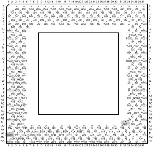
They could be something as simple as LM317T or an equivalent. You could do a bit of measuring with a DMM between VCore and VIO pins on the CPU socket and the three pins of the VRM. VCC2 should be the core voltage, and VCC3 should be the I/O voltage, which will always be 3.3v. Depending on what CPU is installed, VCC2 (core) can vary. On older single rail CPUs, like the original Pentium, this is 3.3v. On split plane CPUs like the AMD K6, Pentium MMX or Cyrix 6x86MX, this can vary between 1.8-3.5v.
Each VRM is probably responsible for one of the VCC2 and VCC3 voltages, you'll just have to figure out which. You may be able to look at other motherboards at the time to get an idea about which linear regulator should be used.
Upgrading and Repairing PCs (17th Edition),2006, (isbn 0789734044, ean 0789734044), by Mueller S.

flylib.com
Description of various pinouts for standard socketed x86 processors.

www.pchardwarelinks.com
As for what voltage capacitors to use, anything above the working voltage. For 5 volts, you can use a 6.3v or 10v capacitor. For 12 volts, you can use a 16v or 25v capacitor. When in doubt, use the original voltage rated capacitor. Don't use a capacitor with too high of a voltage rating, because the internal plate structure changes with voltage and alters the characteristics of the capacitor, as well as the size. So you wouldn't want to use a 50, 63, 160, etc volt capacitor on a low voltage circuit because the size and ESR will preclude them from working properly.
For capacitors in hot areas, you may want to use more expensive solid polymer capacitors. These tolerate heat better if you get 105C or higher rated types. Next to smoking hot linear regulators, or being bathed in hot CPU exhaust, I wouldn't use anything but polymer caps.