• Please review our updated Terms and Rules here

Part # for 9-pin connectors for M8043 DLV11J boards?

GreyHairedDECfan

Experienced Member
Joined
Dec 5, 2021
Messages
127
Location
Northern Maryland
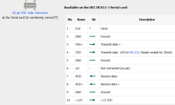
Does anyone know of a generic 9-pin female plug that I can obtain via Amazon or wherever that will work with the DLV11J output connectors? I know DEC made a ribbon cable that connected the 4-port terminal block to these but I can do with just the separate plugs. I just haven't been able to find a part number (did some searching but no dice).
 
And stick a cocktail stick up the missing pin to prevent accidental reversal (if it is not a polarised connector of course)...

Dave
 
Shell: TE Connectivity/AMP 87133-5, DigiKey p/n A26948-ND
Pins: TE Connectivity/AMP 87667-3, DigiKey p/n A3000-ND

These are the original style, but as others have said above, IDC connectors will fit.

-Dave
 
Can someone confirm my pinouts?

IDC DB9

3 XMT - 2 RCV
7 RCV - 3 XMT
5 GND - 5 GND

I'm using the attached document as reference. Thanks.
 

Attachments

  • DLV1J Pinout.png
    DLV1J Pinout.png
    17.6 KB · Views: 6
That doesn't look right to me.

I think (off the top of my head) that you need to connect BOTH pins of RX data. I think one end requires wiring to GND.

I'll check later with the schematics.

EDIT: I was right. Have you checked the DLV11-J manual to ensure the links and wire-wraps are correct to your requirements? See http://www.bitsavers.org/pdf/dec/qbus/EK-DLV1J-UG-001_DLV11-J_Users_Guide_Oct78.pdf.

The Mx and Nx links set each individual port for RS422, RS423, RS232C or 20 mA operation. These are required to be set correctly.

Figure 2-14 (on page 2-25) shows a typical configuration arrangement:

Pin 3 TX (from DLV11-J).
Pin 8 RX (to DLV11-J).

Pin 2 GND connection.

Pins 7 and 9 are required to be connected together on the DLV11-J to make the received data line work. This is done on the associated DEC bulkhead connector - so you will have to do it via a wire link.

Pin 4 (the transmit side) is configured correctly by the Mx or Nx links.

Dave

Dave
 
Last edited:
That doesn't look right to me.

I think (off the top of my head) that you need to connect BOTH pins of RX data. I think one end requires wiring to GND.

I'll check later with the schematics.

Dave
I may have read the image wrong, but I took it as the 2nd set of XMT and RCV pins were for when using a current loop. But again I could easily be looking at this incorrectly.
 
I have updated my previous post.

>>> but I took it as the 2nd set of XMT and RCV pins were for when using a current loop

That's the common mistake :)! They are used for RS422 as well as 20 mA current loop - but are required to be linked to GND for RS232C!

There are too many options on the DLV11-J - so left to either the bulkhead connector or the cable...

See http://www.bitsavers.org/pdf/dec/qbus/MP00586_DLV11-J_Feb78.pdf PDF page 10 of 12 - and look at pins 7 and 8 of each connector. You will observe they are connected to both sides of a receiver (with no GND reference).

Dave
 
Assuming you mean to connect pins 2, 4, 5, 7 and 9 together I observe the following:

Pins 2, 5 and 9 are already connected to GND on the DLV11-J itself.

Pin 4 is configured to GND by means of the Nx link.

This just leaves pin 7 to be connected to GND.

In fact, I now remember some cables I made up once - they had three individual wires (GND, TX and RX) to the remote equipment and a single link on the 10 way connector for the other side of the receiver to GND.

Dave
 
Fortunately I have a bunch of the blue jumpers from a previous life so I'll configure one of the boards correctly (including not as the console device) and try her out. I don't have a wire wrap tool (never thought I'd remotely need one, this far down the line!).
 
Sensible...

Order yourself a manual wire wrapping/unwrapping/stripping tool and some compatible Kynar wire at the same time. You will need it with DEC equipment...

I placed a contract to remanufacture some cards we use at work. They have wire-wrapping configuration spills. The technicians at the manufacturing plant had to be taught how to wire-wrap to the appropriate Standard. They couldn't quite get the correct wrap - until I pointed out that they were using the wrong gauge wire for the spill and tool.

Dave
 
Back
Top