• Please review our updated Terms and Rules here

PC-XT Clone - HELP Repairing Battery Damaged Traces

ayandon

Experienced Member
Joined
Aug 10, 2022
Messages
52
Location
Kolkata, India
Friends,

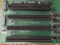
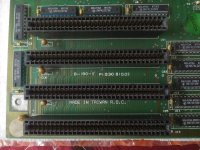
I am trying to repair the Battery Damaged PCB Traces in the Battery area of this PC-XT Clone motherboard.
As I do not have any other reference, I will highly apricate if you can give your keen eyes and experience and draw me a trace diagram on the attached picture to guide me.

1674882572802a - Copy.jpg

It will be a great help and support.
Thanks in advance.

P.S. Ignore those damaged sockets... they are replaced.
 
You don't mention what board it is. But even if known, I don't suppose there will be a schematic for it. The best course of action I would have thought, is to remove everything within the yellow square (and probably a bit further) and then check all the traces etc and fix as necessary.
 
Its Copam B-190 / Copam MC-2031 MXT1
 
Made in India, fascinating. The damage looks significant, but with some patience and effort I think it should be repairable... it's certainly one that I'd not give up on.
 
Made in India, fascinating. The damage looks significant, but with some patience and effort I think it should be repairable... it's certainly one that I'd not give up on.
I have TWO of these boards.
One is Made in India, another is Made in Taiwan.

P.S. these pics are before soap washing.
 

Attachments

  • IMG20221116110654.jpg
    IMG20221116110654.jpg
    1.7 MB · Views: 18
  • IMG20221116110716.jpg
    IMG20221116110716.jpg
    2.1 MB · Views: 18
If you have two boards and one is working (you didn't mention it was not), the rest is obvious: compare all traces. Not just visual but use an Ohm-meter as well.
 
Even then it can be done because I don't expect them to be in exactly the same condition. What will help is to desolder the sockets and ICs surrounding the place of the crime. What also will help: find out the function of these ICs and find their counterparts in the schematics of the IBM XT and/or its clones. Then you what pin should be connected to what pin of another IC. For example: you can start with those 33 Ohm resistors. They most probably have been connected with one side to the various pins of the DRAMs. If not, you could have found a breach. And you find out where the other side of the resistors go to. And so on.....

Good luck!
 
Back
Top