• Please review our updated Terms and Rules here

PDP-11/05 DC Regulator Module (5409728) cable routing

thunter0512

Veteran Member
Joined
Sep 27, 2020
Messages
1,027
Location
Perth in Western Australia
While restoring and repairing a low-profile PDP-11/05 I had to remove the DC Regulator Module PCB designated 5409728 to repair the 5 V rail.

After successful repair of the regulator I am struggling to reinstall the PCB into the steel U-profile power chassis. The two smaller electrolytic capacitors squeeze onto Mate-N-Lok connector and/or its cables coming from the primary side of the transformer and going to the switch & fans.
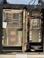
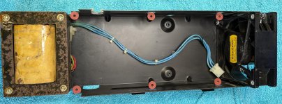
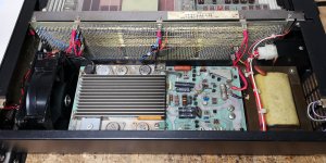
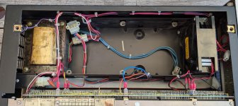
I took the following photo after removing the PCB:
PXL_20240804_083052226.jpg

The offending Mate-N-Lok plug & socket is visible right next to the transformer. Above it is the unplugged Mate-N-Lok plug which plugs into the DC Regulator Module PCB (this one is quite tight too).

I spent about 2 hours trying to arrange the cable harness in different ways but never managed to reinstall the regulator PCB laying flat on the 6 supports. The two capacitors on the PCB near the transformer always interfere with the cables and Mate-N-Lok plug & socket.

Has anyone successfully reassembled this PCB into the chassis?
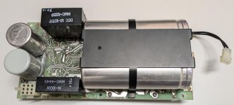
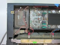
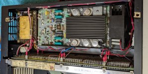
PXL_20240806_153727284.jpg

Note the two electrolytic capacitors on the left which are about 5 cm high and interfere with the Mate-N-Lok shown in the previous photo. The photo also shows the 9 pin Mate-N-Lok socket for the DC output which will receive the plug visible in the previous photo.

Thanks for any help or suggestions.
 
This is pretty different from the 11/05N which is in the taller case, however it uses the exact same regulator board so I may be of help here. It took a bit of adjusting to get the thing to fit in the power supply sub assembly.

Could you adjust the mate N lok connector to sit underneath the transformer or away from the caps?
 
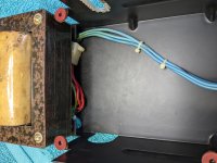
I faced the same issue when re-installing the regulator board in my 11/05. Alas, it's been so long since I did it, I can't remember exactly how it went together. However I do have this picture which hints at the location of the connector being aft of the capacitors and slightly under the transformer. Hopefully this helps.

PDP-1105 #4.JPG
 
Thanks @Dare and @gnupublic for the photos and suggestion. I don't understand why DEC made this such a tricky fit. In the center of the solder side of the PCB there is plenty of space between the two smaller capacitors and the larger capacitors for the Mate-N-Lok connectors to take residence but the cables are too short to reach there. I guess when the unit was newly assembled the cable insulation was more pliable, so it was easier to arrange the cables and connectors. After 50 years the cables are very stiff to work with.

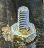
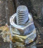
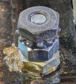
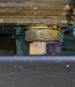
Anyway, I think I came up with a workable solution. I removed the power supply chassis, and from the bottom removed the 4 nuts holding the transformer to the power supply chassis. I then placed an oversized metric nut loosely over the 4 threads protruding from the base of the transformer. I then reassembled the transformer into the power supply chassis, effectively raising the transformer by about 4 millimetre. This extra space should allow me to push the primary side power cable Mate-N-Lok arrangement under the edge of the transformer. This hopefully means the connector will no longer interfere with the two capacitors.

I have also glued a new flexible grommet into the power supply chassis replacing the damaged one which protects the primary side power harness going to the fan and power switch. I will wait until the glue sets before attempting the reassembly of chassis and then PCB.

Here are some photos:
PXL_20240807_075803499.jpg

PXL_20240807_075811808.jpg

PXL_20240807_075826464.jpg

PXL_20240807_080438700.jpg

PXL_20240807_081627809.jpg

PXL_20240807_081758768.jpg
 
FWIW, I'd steel-wool those transformer laminations and apply a coat of black enamel paint to fix the remaining rust in place. Possibly just a coat of Rustoleum primer would be fine, but IMO for this application I'd use an enamel and paint brush to go directly to a better looking, and potentially safer, result. YMMV, of course :-}.
 
This power is also used in the PDP8/F and PDP8/M and I had troubles with the Mate-N-Lok connectors. In my 8M the +5V pin was toasted. Also in both of my 11/20 machines the +5V pin is routed trough one power pin in the connector. The power wires to the backplane are very thin as well. To get 5V on the backplane I had to set the power on 5.6V. And when I added a card, the power dropped again because of the loss in the connector and cables. So this is just too weak. In all these machines I've added a few extra wires for the GND and +5V.

Here you can see what I've done in my PDP11/10 (which is the same as your PDP11/05). I've added two GND and two +5V wires directly trom the 5V output capacitor to the backplane. This solved the power problems for me in several machines.


IMG_20200710_211800.jpg

So now I can add and remove cards without readjusting the 5V power supply.

IMG_20211217_090549.jpg

Regards, Roland
 
This power is also used in the PDP8/F and PDP8/M and I had troubles with the Mate-N-Lok connectors. In my 8M the +5V pin was toasted. Also in both of my 11/20 machines the +5V pin is routed trough one power pin in the connector. The power wires to the backplane are very thin as well. To get 5V on the backplane I had to set the power on 5.6V. And when I added a card, the power dropped again because of the loss in the connector and cables. So this is just too weak. In all these machines I've added a few extra wires for the GND and +5V.
As mentioned, the PDP-8/M has the same regulator board and same deficient +5V power wiring and burning around the +5V Mate-n-Lok connector pin. I also implemented Roland's fix of doubling up the power wiring in my 8/M. It works great!
 
Thanks for all the replies.

@pbirkel@gmail.com the PDP-11/05 was exposed to horrible conditions. There was a lot of corrosion and filth. My first pass through the machine was disassembly followed by a thorough clean with brush, compressed air and isopropyl alcohol. I found a lot of disgusting stuff in the machine. My second pass through is trying to get it operational including dealing with some of the corrosion on the PCBs. The final pass will be removing residual rust and cosmetics like repainting the transformer etc.

The glue holding the flexible grommet has now dried and I have re-fitted the PCB without much trouble with the primary side Mate-N-Lok connector mostly underneath the transformer. So if you are struggling with fitting the power supply PCB in a PDP-11/05, simply remove the transformer and add a spacer such that it lifts the transformer a few millimetres. Earlier I tried for two hours to fit the PCB and started to worry that I might end up damaging the wiring or PCB. With the raised transformer the exercise was almost trivial.

Here is a photo of the PCB nicely fitted. Previously only 3 bolts held the PCB to the chassis, so obviously someone before me must have made an attempt at fault finding of the bad 5 V rail and subsequently failed to fit all 6 bolts.


PXL_20240807_100551619.jpg

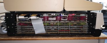
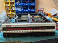
And here is a photo of the system powered up without any PCBs fitted to the backplane, but all LEDs are lit and fans blowing - first sign of life (all power rails are at their appropriate level):

PXL_20240807_100604794.jpg

The old towel is there to prevent the heavy metal frame from sticking to the rubbery anti static mat.
 
Last edited:
Back
Top