• Please review our updated Terms and Rules here

PDP-11/15 revival

coremem

New Member
Joined
Mar 24, 2025
Messages
8
Hi All,

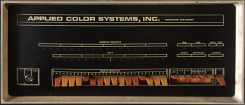
I'm gearing up to take a shot at resurrecting an old 11/15 which I saved from the dumpster about 30 years ago. It has just been sitting on my shelf since then and I'd love some ideas to get me started in the right direction.
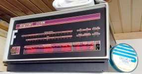
FrontPanelL.jpg

At one point it fired up and responded correctly to some front panel toggling. Last time I powered it on it +5V failed to come up and I quickly shut it off. I suspect that the first order of business will be to take a good look at the power supply. I learned to program on an 11/35 but I'm not an electrical engineer so this will be something of an adventure!

This machine appears to have been an early version of a workstation at Carnegie Mellon. The names on some of the custom boards include founders of Three Rivers Computer (PERQ, which spun out of CMU) so there may be some history there. At least it has a lot of custom boards in it relating to tablet I/O and perhaps early networking? Is that what the Asynchronous Line Interface is? I'm not sure what UMBAWA stands for...

The backplane is almost full:
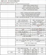
Boards.jpg

Any leads on a replacement deposit switch and an easy way to rig up some (real or emulated) disk or tape storage? Suggestions on what my first steps should be?

Thanks!
-Bill
 
Wow, another PDP-11/15, awesome! The module layout in mine (rebadged as the FOX 2 by FOXBORO) is mostly the same apart from the special cards, but you have a KE11-A...
According to the label on the back of mine it had one once. If possible I would really appreciate seeing some good photos of the modules back and front, backplane etc.
It would be a pipe dream to wire-wrap or KiCad a clone as the KE11-A is required to run Unix v1 (although thanks to Josh Dersch the Unibone can do it now).

Mine has the M7217 PWR FAIL & RESTART card and M7218 MULTIPLE BUS REQ FLOW (4-level interrupt) card to bring the KC11 closer to KA11 PDP-11/20 capability. I do have the 11/15 print set to be scanned sometime.
 
Last edited:
Wow, another PDP-11/15, awesome! The module layout in mine (rebadged as the FOX 2 by FOXBORO) is mostly the same apart from the special cards, but you have a KE11-A...
According to the label on the back of mine it had one once. If possible I would really appreciate seeing some good photos of the modules back and front, backplane etc.
It would be a pipe dream to wire-wrap or KiCad a clone as the KE11-A is required to run Unix v1 (although thanks to Josh Dersch the Unibone can do it now).

Mine has the M7217 PWR FAIL & RESTART card and M7218 MULTIPLE BUS REQ FLOW (4-level interrupt) card to bring the KC11 closer to KA11 PDP-11/20 capability. I do have the 11/15 print set to be scanned sometime.
As I recall (it’s been a while and I’ll have to dig it out) my 11/20 has a KE11-A.

While at CMU the GDPs were special (vector) graphics HW (in a separate box) that were run by an 11/20. You could tell from the performance which ones had a KE11-A. The “cheap” GDPs had 10-bit DACs. The “good” ones had 12-bit DACs.
 
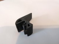
That switch shape is used on several different PDP models. See Vince's Archive of 3D shapes.
I second that idea to used Vince's 3D shapes. I had some of his switch handles printed by JLC3DP and they turned out well,, printed in nylon, I think. Would have to check the order history to confirm. The only thing is the color choices were gray or black. There may have been some detail with JLC complaining about multiple shells, I don't recall, but eventually manipulated the file so they could print it without any issues. Anyway, that can be a quick fix to get you running and you can worry about a proper color replacement later.
@coremem I probably have an extra that I can send to you for the cost of postage
 
Last edited:
Suggestions on what my first steps should be?
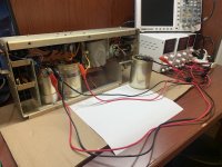
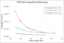
Cleaning inside and reforming the large electrolytics in the power supply.

This was my first attempt at reforming and didn't collect data as well as I would have liked:

Better data collection while restoring a different machine but the explanation of what was done is less through:
 
Last edited:
At least it has a lot of custom boards in it relating to tablet I/O and perhaps early networking? Is that what the Asynchronous Line Interface is?
Asynchronous Serial Line Interface (ASLI) is what we now generally refer to as a UART although 20mA current loop was an alternative to TTL/RS-232 output. The M780 was a discrete component UART blazing along at 110 baud; Teletype-suitable. The custom "ASLI" module was likely more in the range of 9600 baud, possibly intended as as serial link to the host processor (likely a PDP-10). This unit was likely located near users (graphics tablet, special keyboard) rather than adjacent to the host so a faster parallel interface wouldn't have been possible.

I'm not sure what UMBAWA stands for...
No idea, but obviously that home-brew board is combining the M105 address selector and M7821 fast interrupt control. There were third-party modules that did this as well (e.g., Tennecomp TP-142-41). One suspects based on some of the other markings that "UMWABA" was a local tongue-in-cheek acronym :-}.

The "Cranberry Mellon" module seems to be intended to extend the limited core capacity of 4Kw. UVPROM? What is the type and total capacity? I wonder what environment was used to develop the ROM-able code to populate it.

Note that despite the presence of the KE11-A there are no provisions for a graphics display. Perhaps the "ASLI" interface rather than communicating to a host was driving a serial-interface graphics display?

Are there any dates on the chassis rear that might help us place the "era" of first use? Given the front panel "F" marking I imagine that there were "A" through "E" PDP-11s there at CMU as well at that time ...
 
Nice!

In 2021 I started with my PDP11/20 machines, both running fine now. Maybe my story has any helpful information for you...


One of them is on YouTube

Regards, Roland
 
Thanks All for the great info! Now I have to get that thing off the high cabinet and onto the bench and it weighs about 2 tons :)

I just printed a switch (thanks ftcnet and gwiley!) to get me started. I'll probably make a prettier one later:

IMG_20250325_095757_319.jpg

Is it worth the effort to reform the caps? Or is the better part of valor simply replacing with new?

How about the UniProbe and UniBone boards from retrocmp? Recommended?

I'll update with pics soon. Thanks!
-Bill
 
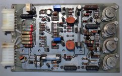
Some immediate problems on this H720E regulator board. Disintegrated axial 330 uF caps on the +5. On the backside the leads look like those missing caps had been reworked/replaced before. A damaged connector trace and some hot connector pins to clean up. Maybe time for those four 150 uF axials to go too? What else should I check on this board?

RegulatorBoard.jpg
 
Is it worth the effort to reform the caps? Or is the better part of valor simply replacing with new?
How about the UniProbe and UniBone boards from retrocmp? Recommended?

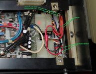
Both of my 11/20 have the original caps and they are fine. But off course I don't know the state of yours. Pay attention to the connectors on the power. I've added wires for the GND and +5V from the power to the backplane wiring. The single pins in the white connectors are quite weak. I've connected the added wires directly to the power PCB. The added wires are in parallel with the original connector pins.

IMG_20210429_140834.jpg

If you want to use RS232 on a M7800 you need to add a G8000 board and route the -15V to the serial board on the DD11A backplane.

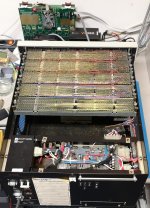
I have four Unibus PDP11 machines and in all machines I have the Unibone. So, yes recommended! You can max out the available memory, you can run tests, emulate disk and tape units. Very useful! But pay attention to the DD11A backplane. AC-low and DC-low are not routed trough the DD11A backplanes, but the UniBone needs these signals to trigger bootstraps. And don't forget to route the NPG trough the DD11A backplane, because the UniBone needs this also. In the early days it wasn't expected that a single board needs the NPG signal. If you run the Unibone on an external DD11CK, these signals are covered.

I have modified both of my machines with these signals with a few hours of wire wrapping. Fun to do and it makes the PDP11 so much more useful with an internal UniBone. For testing I would advise to keep the UniBone externally on a DD11CK. In that way you can keep Linux running, and you can turn on and off the PDP many times for testing... I did that also:

IMG_20210429_141432.jpg

A KM11 might be useful too... I have the originals here, but to be honest, I don't really like them. They are quite bulky

IMG_20201127_141819.jpg

For the KM11 Joerg has a nice KM11 clone design too.

But it all depends on what your plans are with the machine... :)

Regards, Roland
 
Both of my 11/20 have the original caps and they are fine. But off course I don't know the state of yours. Pay attention to the connectors on the power. I've added wires for the GND and +5V from the power to the backplane wiring. The single pins in the white connectors are quite weak. I've connected the added wires directly to the power PCB. The added wires are in parallel with the original connector pins.

View attachment 1298169

If you want to use RS232 on a M7800 you need to add a G8000 board and route the -15V to the serial board on the DD11A backplane.

I have four Unibus PDP11 machines and in all machines I have the Unibone. So, yes recommended! You can max out the available memory, you can run tests, emulate disk and tape units. Very useful! But pay attention to the DD11A backplane. AC-low and DC-low are not routed trough the DD11A backplanes, but the UniBone needs these signals to trigger bootstraps. And don't forget to route the NPG trough the DD11A backplane, because the UniBone needs this also. In the early days it wasn't expected that a single board needs the NPG signal. If you run the Unibone on an external DD11CK, these signals are covered.

I have modified both of my machines with these signals with a few hours of wire wrapping. Fun to do and it makes the PDP11 so much more useful with an internal UniBone. For testing I would advise to keep the UniBone externally on a DD11CK. In that way you can keep Linux running, and you can turn on and off the PDP many times for testing... I did that also:

View attachment 1298170

A KM11 might be useful too... I have the originals here, but to be honest, I don't really like them. They are quite bulky

View attachment 1298171

For the KM11 Joerg has a nice KM11 clone design too.

But it all depends on what your plans are with the machine... :)

Regards, Roland
Hey! I have nice clones too with overlays ((but they’re in short supply now). ;-)
 
Some immediate problems on this H720E regulator board. Disintegrated axial 330 uF caps on the +5. On the backside the leads look like those missing caps had been reworked/replaced before. A damaged connector trace and some hot connector pins to clean up. Maybe time for those four 150 uF axials to go too? What else should I check on this board?
Do take the time to reform the large electrolytics. That regulator has had a hard life! The fully-loaded chassis probably responsible for the connector overheating. Agree with Roland about the bypassing arrangements, particularly so in your case.
 
Last edited:
I completely forgot about these small electrolytics on the power supply pcb. I replaced them all... The big cans with screw terminals were fine.

Regards, Roland
 
Thanks all for the super-helpful advice! The two big cans seemed to come back after a little reforming. At least, they're only pulling about 0.2 mA at 30 Volts so I suppose that's fine. They both read 24,000 uF on the fluke. New little axials are on the way from DigiKey. Beefing up the wiring is a great suggestion since these connectors were perhaps undersized to begin with and that was 54 long years ago...

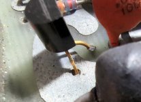
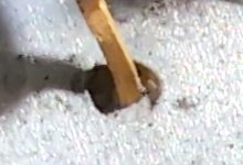
Looking at the power regulator board I see some through-holes that look like this:

PlaneConnections.jpgPlaneConnections2.jpg
That transistor lead punches through that power pour and is soldered to a floating pad on the bottom side of the board. I assume a connection to the power pour is intended but it hardly seems to be much of a connection at all? Those holes in the PCB don't seem to be plated through? I'm tempted to flux these connections up and solder them on the top of the board. Is that a dumb idea?

Thanks!
-Bill
 
Back
Top