• Please review our updated Terms and Rules here

PDP11/34 unknow cpu details and other

cineman

New Member
Joined
Oct 12, 2012
Messages
5
Hello,
I'm Andrea Galvani from Italy.
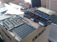
I've came in possession of a lot of PDP11 / 34 parts, from an italian electrical company department,
I hope you can help me in running this computers!
The parts and manuals, and various items are so much we had 2 vans full of things...

I'm trying now to start studying the first pdp11/34, and making some test, reading manuals and the web.
This system was, i think, a lot modified during the years, so i'm not sure what to use or not.
I'm trying to start from the beginning and exclude everything and make basilar test
on the single parts.

I still have no success on seeing a CPU running :( but i made some tests.

here the list of parts i have for now:

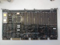
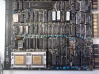
UNKNOWN CPU board with a DEC J11, (photos) called AH-10A-04 . i found no infos around :( registry address, etc ?
1x M8267
3x M8266
1x M8265 ( how to test for sure if working these cpu board ? )

2x M7859 ( i connected these to the bus and programer interface, and seems to work and load his switch register )
3x M7856 ( tried sending byte out, settings dip switch as instructions for my baud etc, I see signal on oscilloscope when depositng bits in 777566 in, but still unsuccesfull to see the character on the PC with a DB25 to DB9 serial. Connected the LA120 to pc and it works, i see char )
3x M7891 ram ? seems to works as i can put address and dep and load

1x M9202
1x M9312
1x M9302
nr 07 grand continuity card

1x M8716
1x M7819
1x M7485+M7486
1x M7547
2x M7792
1x M7867
1x RL02 unit
2x RL82 unit

The UNIBUS has CA1 and CB1 joined everythere aparts location #07 , wich i joined on the M7256 i put there.

Power Supply is OK +-15 and +5.
I connecteed JUST the M7859 programmer console board, and a ram M7891, plus M7303 in #09 and grant board where nothing.

When powered on, I always get a "BUS ERR" signal. Is it ok? I can access memory location and memoryzing in it.

If I put the unknow J11 cpu board, the system start with "BUS ERR" and work as usual, but if i press CTRL+START nothing appen.
If i press CTRL+HLT the "RUN" light goes on, and i have to turn off the system to make it off. Same has having not the cpu board inside.
I tried using M8265+M8266 cpu boards instead of the bigger one, but still no success in running istruction.
Are there any test, or signal path in the unibus, or something with the terminator / boot controller i need to test ?
I have confused ideas of what i really need to use to test basilar CPU istruction :(

Thank you! Hope to start infos exchange... we have really a lot of material to study...and lot more other PDP11 from other
pdp11 computer...
Andrea Galvani
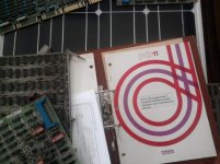
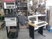
Foto0372.jpgFoto0374.jpgFoto0375.jpgFoto0377.jpgFoto0378.jpg
 
The M8265, M8266 and M8267 FPU are the 11/34A CPU set, the M7859 is the local keypad control that works the front keypad and display on the system and the M9302 is a terminator that fits in the last A and B slot in the system. There is a little sticker on the back of the frame that shows what slots all the cards have to be in. The memory M7891 and communications and clock card M7856 will work in any of the other locations with the M7856 being only in the C, D, E and F locations.
I would remove everything else except that set of cards and get the system working that way first. You will need grant cards, G727 to plug into all the open D row slots or may have to insert some of the other cards you have so the grant signal is carried thru the system. Do you have the 11/34 users guide? Very important book when working with this system. I have a video of my 11/34 with loading a loop program from the front panel on YouTube:
http://www.youtube.com/watch?v=pU8DOKVxDJ8
You system should work about the same although I have noticed that you do not appear to have a M9301 bootstrap terminator card. Is this correct?
 
Hello Qbus, nice to meet you, and thanks for the answer.
Yes, i removed everything and made some test with just basilar cards. I don't have a M9301, but i found on the web that M9312 is a bootstrat terminator too, it should work..?
I had no success in testing the base CPU cards: i never got successfull in seeing a CTRL+START or CTRL+HLT making it RUN and stop, it doesnt want to start. Is there something i can look for, to see if the 2 data+calc boards are working? maybe testing some internal cpu cards registry? what numbers?
Today i checked again that the NPG signal is continuous from the first to the last C, and it is.

When the system was removed, it had the J11 Dec CPU card AH10A-04 inside, so all the other i think were the old ones removed...or maybe even not working :( who know...
 
Not cetin and can be wrong but think the card with the J11 on it may be a complete system on a card. Maybe you remove the M8265, 8266 and 8267 along with removing all memory cards like the M7891 and just keep the M7859 and the M7856 communications card? You will not need the Bootstrap terminator M9301 and everything will run on the J11 card? Don’t know anything about it myself except would think that card makes it into an 11/84 or an 11/94, also have to wonder where it goes in the system. It may want to go into one of the SPC slots and not in the CPU slots 1 and 2, but be warned that I am not a expert and have been having issues of my own lately with system and perhaps one of the more senior members will guide us.
 
Not cetin and can be wrong but think the card with the J11 on it may be a complete system on a card.

It looks like it is a replacement for the 11/34 CPU and memory. Hopefully you have documentation for the
Meiden AHIOA-03 board
 
Item in photos 3&4 is:


  • MEIDEN AHIOA-04 Single Board Computer UNIBUS

Several are listed online in DEC surplus shops. If I recall, it's a smart IO Coprocessor module. I've never seen the UNIBUS version in the flesh.

Did some Googleing, but didn't have much luck. Maybe that will help.
 
It looks like it is a replacement for the 11/34 CPU and memory. Hopefully you have documentation for the
Meiden AHIOA-03 board

I agree this board appears to be an all in one replacement for the original CPU. I have never seen one though.
 
Hello, thanks!
Yes, i thought that the AHIOA was a replacement cpu card... I don't have documentation for now, or at least still not found in the items we have :(
There are 2-3 leds on that cpu board, but if i put that inside, no leds lights. Also, the chips in the last photo, 1190 - 1193 1192 they goes quite hot, not to so much to not putting fingers on, but i wonder if is ok... On the other corner there is chip 1188 , and is not hot, so the cpu is cold. I think i would try to take that chips off and see if some light start to power...maybe too much current in there...
IF the CPU board is functional, what I would expect to see? On power-on, what lights usually lights? buss-err , or it run directly? it should responds to ctrl+start and ctrl+halt, right ? Any standard register in the cpu board i can try to look, to see if memories and something is powered in that board ? Thank you !!
 
Ok... GOOD NEWS :) something works.
cause i dont find much info on the AHIOA, i would like for now to focus on the 2 standard cpu board M8265 and M8266. I have 2x M8265 and 3x M8266.
One of the 8265 had some lines broken and was short on powersupply, i soldered thin wires, repaired it and now no more short cut. BTW is quite difficult sometimes to see if they are short, cause the normal ohm between VCC and GND is around 60-80ohm, so a normal "beeper" is not enought, you have to look close for real 0 ohms.
So, going on, i think i got the 2 cpu card working.
Today i tried this configuration:
slot1 M8266
slot2 M8265
sot 3 M7291 RAM
slot 4 GRANT continuity card in position D
slot 5 M7859 display keypad board
slot 6 grant card in d
slot 7 M7856 serial out + M9312 boot terminator card
slot 8 grant card in d
slot 9 M9303 + grant card in d.

So, powering ON the system, i got no more the "buss err" signal. It start displaying 177777. And now, finally :) the CTRL+START make it going in RUN, and CTRL+HTL makes it halt. I tried with the simplest looping program
loading address 1000 with 5007 or 777 , then starting in 1000 and it loops and stays on!!! great!
I would like now to test more with the serial out, trying sending something out... i still see some signal on the oscilloscope when sending at address 777566 but nothing on the PC terminal :( im quite sure all the dip are ok, setted them on the 3 different cards i have. Maybe i have something wrong in the DB25 to DB9 adapter i made... i hope :) ... i let you know progress ;) thank you bye
 
slot1 M8266
slot2 M8265
slot 3 M7291 RAM
slot 4 GRANT continuity card in position D
slot 5 M7859 display keypad board
slot 6 grant card in d
slot 7 M7856 serial out + M9312 boot terminator card
slot 8 grant card in d
slot 9 M9303 + grant card in d.

The recommended position for the M9312 is in the A-B section of slot 3 as it also acts to terminate one end of the UNIBUS. Slot 7 is not recommended. I would move your M7859 and the M9312 to slot 3, and the M7891 memory to slot 5.
 
Looks like you are making progress, yes you want to set the order of the cards with the M7859 in slot 3, CDEF and the memory in any of the SPC slots and have the M9302 in slot 9 AB. On the DL11 serial card the thing to look at is there are two sets of inputs and out, one set for current loop that works with the ASR teletype and a second set that works with RS-232 and see what ones are selected. The different outputs are on different pins on the ribbon cable. I had to build my own cable for my DL11 but would assume that there are two different cables if they are current loop or RS-232
 
Think I used that same page when I set up the DL11 I have, I can look tonight and copy the settings for my card because I have it set up for con at 9600 with clock enabled and working with the same Dec VT-550 I use for everything. The module test that he has on that web page works great, using the keypad you can examine 777562 and see what you sent the system or enter a value in 77566 and see it displayed on the terminal.
 
Sorry for the delay, have lots going on at work. But am looking at the M7856 right now and this is the switch settings, 1 = ON and 0 = OFF. Switch 1, 1-1, 2-1, 3-0, 4-1, 5-0, 6-0, 7-1, 8-1, 9,-0, 10-1 Switch 2, 1-0, 2-0, 3-1, 4-0, 5-0, 6-1, 7-0, 8-0 Switch 3, 1-1, 2-1, 3-0, 4-0, 5-1, 6-1, 7-0, 8-1, 9-0, 10-1 Switch 4, 1-1, 2-1, 3-0, 4-0, 5-1, 6-0, 7-0, 8-0, 9-0, 10-0 Switch 5, 1-0, 2-0, 3-0, 4-1, 5-0, 6-0, 7-1, 8-0, 9-0, 10-1 This is set up for the port to be the system con and the clock enabled.
 
I have found that setting/resetting 30+ year old DIP switches is no guarantee that they are in the correct state. Pull the board and check across each switch position with an ohmmeter that it is correctly shorted, or not. You may be setting the switches correctly but the logic may not be seeing the correct state if the switch is stuck open/shorted inside.

The check is really simple and saves a lot of hair pulling (should you be lucky enough to still have some left...).

Don
 
Back
Top