- VCF South West - June 14 - 16, Davidson-Gundy Alumni Center at University of Texas at Dallas
- VCF West - Aug 2 - 3, Computer History Museum, Mountain View, CA
- VCF Midwest - Sept 7 - 8 2024, Schaumburg, IL
- VCF SoCal - Mid February 2025, Location TBD, Southern CA
- VCF East - April 2025, Infoage Museum, Wall NJ
-
Please review our updated Terms and Rules here
You are using an out of date browser. It may not display this or other websites correctly.
You should upgrade or use an alternative browser.
You should upgrade or use an alternative browser.
Perkin Elmer 550 Terminal Schematic?
- Thread starter TasKiNG
- Start date

MindWalker
Experienced Member
That looks rough, good luck ") The vent holes on the rear are somewhat recessed so perhaps the insides are not as bad as the exterior.
The vent holes on the rear are somewhat recessed so perhaps the insides are not as bad as the exterior.
I have a working unit (although with a very worn CRT), haven't been able to find a schematic or a service manual. I've added a list of electrolytics into the Terminal wiki's article. The user manual, and somewhat signal-level programming manual is available in here: https://bitsavers.org/pdf/interdata/terminal/550/
The vent holes on the rear are somewhat recessed so perhaps the insides are not as bad as the exterior.I have a working unit (although with a very worn CRT), haven't been able to find a schematic or a service manual. I've added a list of electrolytics into the Terminal wiki's article. The user manual, and somewhat signal-level programming manual is available in here: https://bitsavers.org/pdf/interdata/terminal/550/
Thanks @MindWalker for the link to the programming manual.
The shield on the bottom was missing and it was a barn find so had had alsorts living in it so the boards were quite bad too.
The list of electrolytics will be useful
My main issue is with rust. I can't read the frequencies of the large and small chrystals and cannot read the values of the two large TO-3 style transistors.
If you could identify these for me from your 550 sometime I would really appreciate it.
I have a Perkin Elmer 3210 control panel that I'm putting a pi5 running SIMH interdata/32 (perkin elmer) simulator that I hope to connect this terminal to.
I actually have three of these 550's but they are all in the same state. Good project though
Cheers
Dave
MindWalker
Experienced Member
Perhaps all three won't have the same damages and perhaps you can get at least one good out of them (If you end up with an extra CRT with life left on it, I might be interested )
Can you post an image of the 3210 control panel? Sounds like a neat project if you could hook it up to a Pi.
I looked at my photos of my recapping, the two big TO-3 packages are MC7805CK (closer to the fuse) and MC7812CK. Bigger crystal has 1 8432 BME on it (1,8432 Mhz?), can't quite read what the smaller one says.
(If you end up with an extra CRT with life left on it, I might be interested )Can you post an image of the 3210 control panel? Sounds like a neat project if you could hook it up to a Pi.
I looked at my photos of my recapping, the two big TO-3 packages are MC7805CK (closer to the fuse) and MC7812CK. Bigger crystal has 1 8432 BME on it (1,8432 Mhz?), can't quite read what the smaller one says.
Attachments
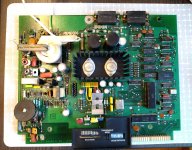
@MindWalker Thanks for the info. Thats a nice looking board. Ah so they are voltage regulators not transistors. Looks quite a simple psu design
On mine, one has some keys missing, one has a cracked case at the rear. and one has a broken tube (you can see the phospor missing on the middle terminal screen).
So If I can get the electronics working I should be able to make two good ones out of the three

Here's my rusty board.

Here's my panel

On mine, one has some keys missing, one has a cracked case at the rear. and one has a broken tube (you can see the phospor missing on the middle terminal screen).
So If I can get the electronics working I should be able to make two good ones out of the three
Here's my rusty board.
Here's my panel

Just desoldered the Main Board / Keyboard electrolytic capacitors.
They were in pretty bad condition i.e. values way out, electrically leaky and also a number had leaked electrolyte.
Here's a record of the locations, polarity and values ( may help someone else in the future )