• Please review our updated Terms and Rules here

PET 2001-32N BS, with horizontal lines.

Muttley Black

Experienced Member
Joined
Aug 4, 2019
Messages
104
Location
Greece
Hello everybody!

First of all please forgive me for my not so well English, it is not my first language. So...

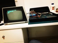
Before two days i got my precious Commodore PET 2001-32N BS. Till now i never had the chance not even see one in real and finally i got one! I take it faulty with horizontal lines on the screen. Photo is from others member thread cause today i take apart the monitor from the case, but i have the same issue.
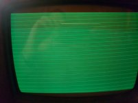
dsds.jpg

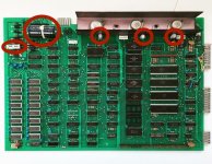
What i find so far is that i missing -5V on ram IC's. I check the voltage regulator and i have output 0v. The input is -10V. One of my questions that i dont want to forget to ask, is that on schematic i see that pet 2001 use 7905 regulator. In my case my motherboard have 7906 regulator. Is that normal?
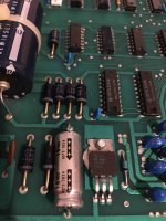
5444.jpg

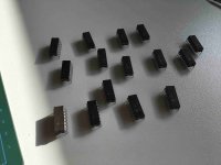
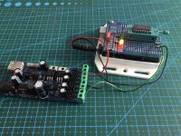
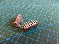
What i did after i saw the missing -5V, is to test the HM4716A-4 Ram's with my arduino tester one by one. Luckily all Ic's are in working order. So, i just clean very well the IC legs and put them away till i fix first the issue with the regulator.
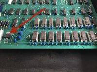
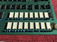
Photo 5-12-19, 12 48 17-min.jpg Photo 5-12-19, 13 25 19-min.jpg Photo 5-12-19, 13 25 23-min.jpg Photo 5-12-19, 13 26 15-min.jpg Photo 5-12-19, 14 47 01-min.jpg

What other things i found in the board are some "mods" that may be tell something to you.

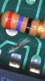
First there is a cut on trace that going at UG6 74LS107 Pin12.
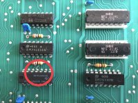
Photo 5-12-19, 10 15 52-min.jpg Photo 5-12-19, 10 33 56-min.jpg

Also, there is a bypass cable that connect the previous UG6 74LS107 Pin12 with the UH6 74LS107 Pin2.
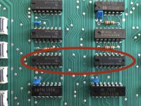
Photo 5-12-19, 10 33 13-min.jpg Photo 5-12-19, 10 16 12-min.jpg

Finally, the is one more cut on the trace that normally connect the UH1 74S74 pin12 with UF1 74LS08 pin3.
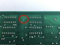
Photo 5-12-19, 10 16 22-min.jpg Photo 5-12-19, 10 33 22-min.jpg


All this i can tell for now. The reason i take apart the monitor from the case in because i read that is very risky to do test's with the original monitor. I am waiting the schematic from here http://www.vcfed.org/forum/showthread.php?71286-PET-2001-32N-Diag-works-in-UD9-but-with-Kernal-it-fails-to-start&p=597230#post597230 to connect an external monitor to the motherboard.

Should i replace the faulty voltage regulator? But with what, 7905 or 7906? And check after the replace the -5v if they come back on board.

I have a voltmeter and i just buy a logic probe, eprom programmer, mini oscilloscope (in the way), in case i need them for the repair.

Thank you all very much for your time reading all this and i really cross my fingers for your help! :)
 
Welcome to the party!

Don’t apologise for your English... Your English will be better than our Greek!

Yes, you need to get the -5V rail back to working order, otherwise you will have no working RAM.

Before I give you any recommendation of my own, let me digest your text and photographs tomorrow to see what I can see in the modifications. It is getting rather late in the UK at the moment, and I am sure it is much later in Greece!

I also hate people who do mods and then don’t leave documentation within the machine telling the next owner what they have done. But that’s another story...

Dave
 
If you disconnect the J7 video connector, your monitor will be safe. With no horizontal drive signal from the mainboard connected to the video board there will be no high voltage. There appears to be no video data being generated. Hopefully that is a problem in the mainboard which can be easily fixed.

Yes, when you replace the 7905 regulator, check that +5V, -5V, and +12V are all working. Then we can see if the 6502 CPU is running. The jumper from G6-pin12 to H6-pin2 is connecting signal /RA1 as the trace was cut to G6-pin12. Perhaps the trace was shorted to something and had to be abandoned? You would want to scope G6-pin12 and see that /RA1 is OK. It will be a square wave of 500 KHz.
 
Thank you both!

I did a mistake. The neg voltage regulator is indeed 7905c and not 7906. Sorry about that. He have both numbers and this confuse me. To be honest, when i read 7906 in the beginning i didn't read the other number.

Now about the Oscilloscope, i order a cheap one. The DSO FNIRSI-150 15001K, the fully assembled one.

With this specifications:

Maximum Real-time Sampling Rate: 1MSa/s
Analog Bandwidth: 0-200KHz
Sensitivity Range: 5mV/div-20mV/idv
Maximum Input Voltage: 50Vpk (1X probe)
Input Impedance: 1M ohms/20pF
Accuracy: 12 Bits
Record Length: 1024 points
Coupling Modes: DC / AC / GND
Time Base Range: 500s/Div - 10us / Div
Trigger Modes: Auto, Normal, and Single
Trigger Position: Center of Buffer
Supply Voltage: DC 9V(8-10V)
Current Consumption:~120mA @ 9V
Main Board Size: 94 * 65mm / 3.7 * 2.56in
Analog Board Size: 65 * 47mm / 2.56 * 1.85in
Screen Size: 52 * 40mm / 2 * 1.57in
Package Size: 14.5 * 10 * 3.7cm / 5.7 * 3.94 * 1.45in
Package Weight: 179g / 6.33oz


I hope i can do my job with this one.

Thank you!
 
What Dave says!

The regulator should be a 7905 and NOT a 7906. Someone may have tried to 'fix' this before and caused more problems for you in the process. EDIT: I see you have identified the correct part now. The 7906 may be the date code (1979 month 06).

As Dave says, make sure you have healthy power rails before doing anything. If you already have the RAM removed, don't plug it back in until you have sorted out the -5V. You may find there is a problem on the board and you don't want to damage the RAMS if you can avoid it.

The oscilloscope you have chosen is similar to what I have. It is OK for video signals and slower - but nothing much faster. We have fixed ilpaninaro's 8032 PET before with a similar oscilloscope and a bit of ingenuity :)!

Dave
 
Last edited:
Power rail always have capacitors on them. These can be shorted. Since you have a voltmeter, I'm sure it can read ohms. With the power turned off, measure the resistance from the output of the regulator to ground. If it is shorted, the resistance will be really low, usually less than 10 ohms.
Two things can cause 0 volts. An open regulator is one. A short to ground is the other.
Dwight

I agree with Dwight, it's far more easy for a capacitor to short than for a 7905 to fail, but all can happen anyway :)
I'd check for shorts on the -5V rail before changing the regulator. Since your board has tantalum capacitors, one shorted capacitor is almost certain.
I've had shorted tantalums in quite a few PET repairs.
The "mods" may actually be corrections on a bad run of 2001N PCBs, I *seem* to remember having seen something similar on one PET I've got to repair, but I can't really recall the details now.
I would first fix the -5V problem, then see what happens next.
Frank
 
Hello everyone and sorry for the late reply, very busy at work.

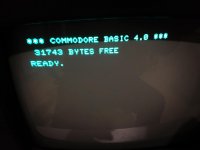
I have good news! I start with what Dwight ask me to check. i found no shorted capacitor's. So i replace the 7905 with ST L7905cv at 1.5A cause i saw datasheet on Texas instruments regulator and it was 1.5A.

I plug the beauty, switch it on and....


df.jpg dfdf.jpg

I am very happy!


I need to open and check the keyboard, because the only key that working is the "space" key.
I have some more questions if you will allow me please. But i write them a bit later.

Thank you all!
 
I need to open and check the keyboard, because the only key that working is the "space" key.

Great work.
There will probably be no need to take the keys all apart. Just get to the bottom of the keys and clean the keypads very well with isopropyl alcohol. Be careful with the many tiny screws holding the key circuit board. Don't leave any screws off when buttoning up the circuit board as a solid mechanical support is needed between the board an the key frame for good operation of the keys.

Thank you!

I prefer to disassemble all the keyboard for clean the keycaps too. I do your steps with isopropyl alcohol and I post the results here.

One more thing I want to ask is the recap. I am looking forward to recap the electrolytic capacitors with good brand like Nichicon for example. It is a good move yes?

AC360339-9BB7-4FEE-A2F2-B676C6555115.jpeg

Also I want to do the same thing on monitor board.
I want to make on this beauty a nice restoration and give him other 40 years of life.
I don’t know if it is normal but if I place my hand in monitor case the time is working, the screen shaking a bit.

If you have any other restoration tips that you thing that i must do on this computer, i do them with pleasure!

Thank you
 
It’s not only the electrolytic that are a problem, the little blue or yellow tantalum beads are more problematic.

If you want to give the PET a better chance of survival then you might like to consider these as well.

However, a word of warning, this is no guarantee that the PET will survive intact for a year, let alone 40...

>>> I don’t know if it is normal but if I place my hand in monitor case the time is working, the screen shaking a bit.

Er, don’t put your hand in the monitor case! Or do you mean on the monitor case?

Dave
 
I understand what you mean about surviving Dave and you are right. I know that it is an old hardware with no guarantee. I just want to replace the components that are more "fragile"? I don’t know if I use the right word.

And yes I meant "on" the case. :p . When I put my hands in top of the monitor case.
 
The metal case of the PET and the monitor should be earthed, so putting your hand on the monitor shouldn’t cause interference.

Is your PET earthed properly?

Sorry, I couldn’t resist the “don’t put your hand in the monitor”... thanks for the clarification.

Dave
 
Ahhh. Of course was not. As the monitor was separated from the body case. As you saw in my photo.:rolleyes:
 
I'm glad to see that replacing the regulator brought it back to life. Still, years of experience has taught me to check all the angles before replacing anything. You should only replace electrolytics that show indications of failing. It is much easier to damage the computer when doing a lot of unnecessary parts replacements. You have a working machine keep it that way.
Dwight
 
Back
Top