• Please review our updated Terms and Rules here

PET 2001-8 220V black screen

Joined
Apr 27, 2023
Messages
23
Location
Cheltenham
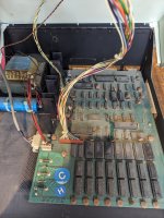
Hi all, I am new to the forum! I have just purchased this PET, and yesterday nervously switched it on. The first time I got the basic screen saying 4032.031 bytes of ram (wrong) and only a few keys working. I pressed enter and got 'error' and the machine froze. So I switched off and back on. This time a flash of random characters and then a blank screen. Dusty board attached! Nervous about another switch on. Shall I clean, remove chips next? The rams are 6550, can I test these? Thanks all!
 

Attachments

  • PXL_20230425_141719253.jpg
    PXL_20230425_141719253.jpg
    3 MB · Views: 15
Hi

Well the good news is that for a moment you got some good behaviour!

There probably is a FAQ somewhere but...

Do the standard things first... check voltages at the voltage regulators... then as it was so close to working... remove the ROMs... maybe a sprinkle of contact cleaner and reseat them. See how far you get.

IMHO the easiest way to have an approximate test of a 6550 is to cycle them one at a time through the video sockets (which are also 6550).

Welcome!

Regards
Nivag
 
Yes, welcome.

You are only just down the M5 from me. I work over in Gloucester (when I am in the office and not working from home that is)...

I have a PETTESTER ROM, but for a 2001 machine you would have to use an adapter to run it.

There are also ROMulators available that also contain my PETTESTER code. These generally fit into the CPU socket.

As Nivag has already stated, you can swap the RAMs around into the video socket (one at a time) but keep track of which device you are testing...

Dave
 
The flash of characters and a blank screen after that, is not a bad thing. You will see it on a normal PET briefly after power up. It means that the VDU is working and that the CPU got its reset pulse. After that the CPU went to boot the machine. If that boot to BASIC process fails the screen will be blank in many cases. This typically can happen when there is a failed RAM IC in the lower bank, or even the upper bank if an output bit is stuck high or low, corrupting the lower bank, because then BASIC cannot run. Could be other issues with defective ROM too, but at least you know that a lot of it is actually working.

I'm not too familiar with the 6550 RAM chips on your board, different than my machine, it uses 4116's. If possible though on your board, if the board has any jumpers for a lower amount of RAM,(less chips, for a minimal machine), you could set it for that and just test smaller groups of the chips you have to try to eliminate the bad ones, then hopefully get some video back. But cycling them through the video sockets as Daver2 suggested is a clever idea.
 
Last edited:
Usually, what happens, is the CPU reset vector is in the 'F' ROM. This initialises the CPU registers and calls the 'E' ROM to initialise the rest of the hardware devices. This also clears the video RAM. It then does a return to go back to the 'F' ROM to complete more work.

The hardware stack is in page 1 of RAM (addresses $0100 to $01FF). If this RAM is faulty, the return doesn't go back to where it is supposed to go to, but to some random location (hence the 'crash').

Dave
 
The hardware stack is in page 1 of RAM (addresses $0100 to $01FF). If this RAM is faulty, the return doesn't go back to where it is supposed to go to, but to some random location (hence the 'crash').

Dave
Somewhat analogous to a Black screen equivalent of a Blue screen.
 
I have a PETTESTER ROM, but for a 2001 machine you would have to use an adapter to run it.
That could probably be arranged.

Also, can we have an idea of your test equipment and experience... what do you have to hand? You can then be guided according to your experience.
 
Hi there, thanks for the feedback!
So I have some experience on 6502 machines. Soldering traces etc. This one I have stripped out the seated rams and ROMs and dusted the board. I then think I'll clean the connectors as suggested above. Also as suggested I will next test the rams in the video and label good bad. To do this I have ordered 6 x 2114 rams and adaptors from laser.com this way I have a good known base as I believe the first 4 lower rams in place is enough to boot basic? And the other 2 can start the video Ram to check I get a clean boot. Is that correct?

Will the machine be happy switching on and off numerous times with video Ram swaps? Don't want to blow it up!

Hi Dave, I also spend time in Broadway!
Thanks Andrew
 
Usually, what happens, is the CPU reset vector is in the 'F' ROM. This initialises the CPU registers and calls the 'E' ROM to initialise the rest of the hardware devices. This also clears the video RAM. It then does a return to go back to the 'F' ROM to complete more work.

The hardware stack is in page 1 of RAM (addresses $0100 to $01FF). If this RAM is faulty, the return doesn't go back to where it is supposed to go to, but to some random location (hence the 'crash').

Dave
@daver2 , something that just occurred to me; Your PETTESTER replaces the EDIT and needs the Kernal to boot the machine and pass control over to the Edit ROM.

- This requires a working Kernal, correct?
- Could it be logical / practical to move the PETTESTER code to the Kernal ROM slot, so only the PETTESTER is needed, basically in the Fxxx block?

I realise this question must've been asked a gazillion times and there's some obvious answer that's escaping me at this point. :)
 
I like the Romulator and the PET_tester systems.

What I decided to do for my broken PET initially, was to make sure all the ROMs were perfect by creating an entirely new set, known to be good from the Zimmers files, using 2532JL and 2716 UV Eproms. I installed those in my machine. Then I made a system which dynamically deactivated the lower 2k of RAM and substituted the lower RAM for known good SRAM, so as to run BASIC and then ran some simple diagnostic programs to check the remaining RAM for defects. The system can weed out the defective RAM's without having to unsolder them. Then I substituted the original ROM's back in one by one to screen out the defective original ones, of which there were a few.

Later I documented all of the waveforms that are important in the (4116) Dram support circuitry in my PET. However, this is different to your board.

One thing that amazes me, is the many variations of PET hardware out there, many of my findings probably don't relate to your PET.

I think though, that for most PET repairs, the Romulator and the PETTEST systems are a very nice tool, because they help people, no matter what the version of the PET, in a systematic manner, home in the fault/s.

If you have any worry about your Kernal ROM, you could always cut a new one from the Zimmers files. Or put your Kernal ROM in the reader and do a file compare, probably better than a checksum.
 
Yes it can. In fact a number of people have done that already by modifying my sources on my Google Drive. Freely available to all...

The reason I did this (initially) is that most of the ROMs are actually soldered in - apart from the EDIT ROM that is always in a socket.

PETTESTER only uses the restart vector and a handful of instructions within the Kernal ROM before it takes control of the machine.

PETTESTER Version 5 will have the option for assembling to fit in the EDIT or KERNAL locations. If assembled for the KERNAL location, it will include additional tests (because the KERNAL ROM is 4K and the EDIT ROM is only 2K (by default)). V5 is a way off yet though I am afraid. Pressure of 'real' work to pay for the hobby.

PETTESTER started out as an experiment and morphed into what it is today because it seems to be so useful. I have added as much as I can in 2K - so anymore involves a bit of a re-write. As Hugo has already said, this code works in pretty much all PETs (the exception being a 40 column PET with a CRTC where a small code change is required to the initialisation table for the CRTC) irrespective of the ROM, RAM and BASIC fitted.

Dave
 
Last edited:
"The reason I did this (initially) is that most of the ROMs are actually soldered in - apart from the EDIT ROM that is always in a socket."
.
^^ The lightbulb answer :)
.
My "PET Test kit" currently consists of:
- A Nicolas Welte RAM/ROM replacement board - have made a number of these for previous repairs with faulty ROMs
- Dave's PETTESTER in a 2816
- NOP Generator
- Dave Curran's amazing PET diagnostics unit. Wish we could convince Dave to make these again.
- A cassette with a program to test/debug the IEEE circuit.
- PET video to composite adaptor
- PET video to HDMI adaptor
.

Must still order a 6502 ROMulator (there is now a Z80 version as well, which is really exciting)

And there is my system for diagnosing defective 4116 DRAM IC's and homing in on the defective chips. Its use comes into play when the IC's are soldered onto the pcb. If they are in sockets, it is much less of a problem as they can be moved around and/or put in a 4116 IC tester. I built it because one of my PET computer boards has all the 4116's soldered in at the factory and I did not want to unnecessarily remove a perfectly good chip.

www.worldphaco.com/uploads/DRAM%20MEMORY%20TEST%20SYSTEM%20FOR%20THE%20DYNAMIC%20PET%20COMPUTER.pdf

One thing I was also going to do, using the same principle of dynamic disabling of the DRAM reads, was to make a plug on SRAM adapter (similar to the one in the article), but with more SRAM chips to the full 32k. Then have their power backed up on the pcb with a backup battery. So the programs would remain intact if the PET lost line power, but I have not got around to that project yet. I tend to build most of my vintage computer projects with period correct parts. The idea is that nothing in the computer looks out of place with respect to the age of it. This is a hangover from a lot of other restoration work I do on vintage TV's radios, amplifiers etc. I try to do it in a way that would have been done at the time the machine was made. It is just an oddball obsession I have.

There is also a lot of information here on 9" PET VDU repairs:


As an example of the madness, I wanted to build an electronic dynamo regulator for my 1966 vintage Triumph TR4A car, to replace the electro-mechanical unit, so I built it from period correct parts to emulate the function of the original unit, but be all solid state:

 
Last edited:
Hi Automaticbirds!

As others have said, welcome to the VCF Forum. You'll quickly find that the crew commenting in this thread above me are the-best-of-the-best.

PETTESTER and/or a ROMulator are both good items to have handy while you own a PET.

The screen of random characters is normal. On a boot from cold, you don't see it since the CRT hasn't warmed up yet. But on a reboot you will.

What you said about minimum required RAM is correct, I1, I2, J1, J2, and the two RAM which handle video at C3 and C4. That'll give you 1023 bytes free on boot.

The fractional BYTES FREE, and now a black screen, suggests bad RAM. Stuck or flipping bits messing with BASIC while its counting up. Were any of the chips hot to the touch? Sometimes when the 6550s fail, they get quite HOT. Diagnostics using an oscilloscope would be good here, less guesswork, but since you didn't mention it I assume you do not have one. And that's OK, we can still fix this.

I'd pull all the RAM out except the 6 chips I mentioned above and then power it up. Assuming that works, you can reintroduce RAM in pairs (I3 and J3, then I4 and J4, etc) until it stops working. and you'll then have narrowed it down to two suspect chips. If it doesn't work, swap the 4 at I1, J1, I2, J2 with others you pulled and try again. It's also possible more than one RAM is bad. One PET I just restored had 5 bad 6550s, of the 18 installed.

Its not great for the PET to power it off and on frequently, but you have to while swapping chips. I don't know numbers, to say how many power cycles is too many. Just be reasonable.

The issue with the BYTES FREE is probably unrelated to the keyboard. Once the machine is booting properly, we can work on that problem. Could be a decoding issue, but more likely the keyboard needs a good cleaning.

Keep us posted on your progress!
 
Good explanation.

You can fit a manual reset button to the PET for just this eventuality.

You solder a normally-open pushbutton across capacitor C6 (0.1 uF) close to the 8-pin 555 reset timer.

Dave
 
In reality there is little harm done de-powering and re-powering the PET.

That is, if you don't switch it on & off within a few seconds, if you wait 10 to 20 seconds it is in fact ok.

If it is rapidly done, some high intensity bright flashes are a little harsh on the CRT phosphor.

The VDU for example, has no problem because CRT heater is warm, so the turn on surge current there is lower than when you do it from cold.

The same applies elsewhere in the power supply circuitry; surge currents charging filter capacitors are lower than when they have zero initial charge when the PET has been left off for hours. Some residual charge is not unhelpful.

I'm not sure why somebody said that it is bad to power cycle the PET at its main power switch.

The only reason I could think of, that could cause any harm, is that the line power switch would wear out more quickly.
 
The challenge is to wait that 20 seconds as you are doing debugging when you just want a quick reboot. Definitely better to fit a reset switch and keep all the supply lines stable. I added this reset switch to my 2001 for testing. And might just leave it in..
.
Noob question: What's the purpose of the LED.2001-Reset-02.jpg
 
Back
Top