Point 7 is the final drive to the scan coils. This should be a 12V or so signal.
No signal here at all means no vertical deflection on the CRT screen, so I don't believe there is not a signal here...
As this is the final drive to the Y scan coils, you should be able to see your disturbances. You then work backwards...
Dave
Dave, in this case though, because the disturbance is inside the feedback loop, it will appear everywhere in the vertical scan amplifier stages, and that will also alter the input conditions a little too, the feedback is passed directly to the base of the input transistor, making it look as though there is a small disturbance on the V drive signal at the input. So tracing the signal back from output to input might be less helpful than usual.
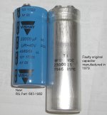
As I recall when my PET was doing this, the phase errors in the V drive signal from the main computer board were not that obvious on the scope. The borderline breakthrough ripple in the 5V regulator outputs, due to the capacitance in the 23,000uF being borderline low, was just enough to fractionally alter the timing in the drive pulse generator counters & logic. The computer otherwise was functioning normally. Lifting the line power voltage to the PET with a Variac would quickly show this was the problem, or eliminate it as a possible cause. If it was not the cause, the next thing I would check is the DC voltage on the /INIT line, to make sure it was a good logic high around 4V and not sitting somewhere around 1.5 to 2V to eliminate that.
One other method would be to replace the V drive signal to the the VDU with one from a pulse generator circuit that produced the correct frequency and correct amplitude and duty cycle of the original pulse. That could be a little time consuming to set up, but it would isolate the problem to either inside or outside of the VDU. Or obviously try the VDU on another PET computer if there was one available.
I'm still suspicious that the main 23,000uF filter cap is not ruled out yet.
Also, in the VDU, I think if the capacitor C15 was failing and going low capacitance and or high ESR, the scan height would obviously drop and the + feedback would reduce. Though if R32 the 2,2R current sensing resistor was going a little high, the +FB would increase, so worth checking that.
But I'm thinking that the problem is less likely in the VDU itself, the reason being that this oscillatory behaviour is intrinsic to this VDU and it does not take much of a vertical drive signal error to set it off.