• Please review our updated Terms and Rules here

PET 3032 Repair

eight088

Experienced Member
Joined
Oct 31, 2018
Messages
158
Location
Perth, WA Australia
Hi everyone

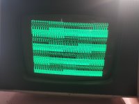
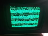
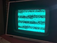
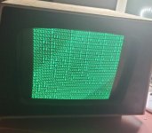
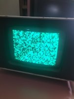
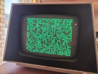
So my next attempt at a repair has begun! I have a 3032 pet that I'm trying to get working after having just fixed the vdu. Initial symptoms are a garbage screen when first flicked on, then the screen changes to predominatly % and $ symbols.

From a previous post daver2 asked to check the following -

daver2 said:
The next place to check with your oscilloscope is on the 6502 CPU.

Pin 2 (RDY) should be HIGH.
Pin 4 (/IRQ) should either be HIG or pulsing - put not permanently LOW.
Pin 6 (/NMI) should be HIGH.
Pin 7 (SYNC) should be pulsing (if the CPU is executing instructions).
Pin 38 (SO) should be HIGH.
Pin 39 (/RESET) should be LOW when you first turn the PET on, and then go HIGH after about half to one second.

Let's see where that takes us.

I can report back that

  1. Pin 2 is high
  2. Pin 4 is low (starts high when the system is turned on, then goes permanently low)
  3. Pin 6 is high
  4. Pin 7 is pulsing
  5. Pin 38 is high
  6. Pin 40 (I think you meant 40 instead of 39) is low then high.
So it seems like the /irq signal is being held active? Would that make one of the 6520's or the 6522 suspicious? Can I remove them and observe the signal on the 6502?

daver2 also asked -

daver2 said:
Do you have the capability for burning EPROMs?

Unfortunately I do not. Would a tl866 do the job? I've been wanting to get a programmer for a while, and I might grab one of these if it will suit the type of eproms I will need to use.

Cheers
 

Attachments

  • working!.jpg
    working!.jpg
    33.3 KB · Views: 9
Welcome back to the next thread...

Yes, I did mean pin 40 for the /RESET signal not pin 39. I also meant to include pin 39 as the 1 MHz clock from the 6502. This is not required as we see pin 7 pulsing.

OK, so pin 7 pulsing indicates that the CPU is executing instructions (which is good).

Pin 4 (/IRQ) is definitely suspect!

I concur with your suggestion of removing the 6520 and 6522 devices. I would suggest removing the PIAs for the KEYBOARD and IEEE488 ports first and see if that fixes the problem.

The TL866 supports the 2716 (single rail) type of EPROM.

A single rail (+5V) 2716 EPROM is fine for fitting into UD8 (which should be the EDIT ROM and be labelled as a 6316 ROM).

I am 99.9% convinced you have something wrong with the video RAM and/or associated logic. The characters are good - indicating the H and V video drives signals, the character generator and the video shift register are good. The display is also not the usual RANDOM character display - so the CPU thinks it has cleared the video memory to all BLANKS - but that has not actually occurred properly. There is also a repeating pattern I can see - plus some 'random' characters thrown in for good measure.

I will just lookup the PETSCII for a SPACE and a '%' character to see if that tells us something...

Dave
 
The PETSCII characters are coded as follows:

Code:
[SPACE] = $20 = 0010_0000.
'$'     = $24 = 0010_0100.
'%'     = $25 = 0010_0101.

This looks like the LOW nibble of the video RAM contents somewhere is not correct.

This could be either faulty video RAM (F8) and/or buffer(s) E8 and/or E9.

We won't know which until you get something operational - either BASIC (without the permanent interrupt) or my PETTESTER.

Dave
 
Your knowledge is invaluable Dave!

The two memory chips at F8 and F7 have previously had some work done on it, and the soldering is disgusting. I might remove them anyway, put sockets in and put a couple of new 2114 chips which I received today in the mail, in anticipation that they might be bad. Potentially good timing!

Cheers
 
Sounds like a plan to me...

Poor soldering = more unreliability and work for the future anyhow.

Dave
 
Well I had to wait till this morning because I didn't have any 18 pin sockets. Went and grabbed a heap this morning, and put the new sockets in with "new" 2114 chips. I also removed C7, and the /int line on the cpu now sits high. I swapped the 6520 that was in c6 into c7, and noticed the same original behaviour on the /int pin. Starts high and then goes low.

So with new video ram and c7 removed, still get a garbled screen, but it's different. Picture attached.
I've also attached what f7 and f8 originally looked like. Zooming in on it looks like pins 17 and 18 on f7 might have been shorted. I missed that the first time I looked at it. Guess my eyes are starting to age more than I thought lol

Also, unfortunately the vdu still has a problem. It seems to loose 12v after being on for a certain amount of time (haven't timed it yet but it would most likely be more than 3-4 minutes).

Cheers
 

Attachments

  • bad video ram.jpg
    bad video ram.jpg
    523.7 KB · Views: 9
  • new video ram and no c7.jpg
    new video ram and no c7.jpg
    171.9 KB · Views: 9
That random screen looks a bit better now...

Probably the monitor regulator is overheating. Either the monitor is drawing too much current or the thermal paste, heatsink mounting arrangement etc. is not dissipating the heat too well. Or the regulator is faulty.

I'll have a think about the PIA issue. I am on a business trip at the moment, so limited access to things other than my (fading) memory!

Dave
 
Okay so I think I now have the vdu fixed. Again. It was the wire from the the mainboard to the monitor. The video signal wire was dodgy on the monitor end. It was the first thing I tested, but in a certain position it was fine, little bit of pressure it was no good. Now fixed and seems much more reliable.

Unfortunately, when the screen came up, I now have a similar screen to before I swapped out the video ram - slightly different though (photo attached). Feels like when I make one step forward, it is followed by two steps backward!

I think the next best course of action is to get the pettest rom. Will a 2816 chip work for the pettest? I _might_ be able to get one, which will probably help me to go further.

Cheers
 

Attachments

  • 1step 2 back.jpg
    1step 2 back.jpg
    234.6 KB · Views: 4
Wish I could pay it forward and send you one! But I'm in the US, and shipping to Australia is awful. Expensive, and takes a month if it gets there at all. I shipped a C64 power supply to a guy and it disappeared for 6 months before finally showing up!

Anyway, the PETTEST ROM (and Dave's guidance) was invaluable for me to get my recent 8032 repair completed. Also excellent that it goes in the EDIT ROM socket.
 
Just want to double check what rom I can use to put the pettest on. I was looking at the roms on my board, and they are 901465-01 in D9, and I have seen that these are the same as a tms-2532. I compared the pinouts of a 2532 and 2816, and a couple of pins are different. If I used a 2816 would that mean I would need an adapter?

Cheers
 
Wish I could pay it forward and send you one! But I'm in the US, and shipping to Australia is awful. Expensive, and takes a month if it gets there at all. I shipped a C64 power supply to a guy and it disappeared for 6 months before finally showing up!

Anyway, the PETTEST ROM (and Dave's guidance) was invaluable for me to get my recent 8032 repair completed. Also excellent that it goes in the EDIT ROM socket.

Thanks for the thought Kevin. Hopefully I can find someone on this side of the world to program one for me!
 
Just want to double check what rom I can use to put the pettest on. I was looking at the roms on my board, and they are 901465-01 in D9, and I have seen that these are the same as a tms-2532. I compared the pinouts of a 2532 and 2816, and a couple of pins are different. If I used a 2816 would that mean I would need an adapter?

Cheers
The EEPROM 2816 is compatible in the PET because pin 21 (/Write) is held at +5V which means it it will be the same as a read only ROM.
Pin 18 is a chip enable in the 2816 and as it connected to address A11 in the PET, that line will be low when the Edit ROM is needed to be used (E000 to E7FF) in conjunction with /SEL E, and high when not needed.

Also by a happy quirk of pinouts, the 2732 EPROM can be used in the EDIT socket as is, if the 2K data is programmed into the upper 2K of the 4K EPROM ($800-$FFF).
 
Last edited:
I would recommend that you get a GQ-4x programmer from ebay, they are not expensive and they program the 2716 and TMS2532JL UV eproms very well. This way you can make a spare ROM set for your computer and make Dave's Pettester ROM too. Having a known good set of ROMs will help save you plenty of time in fault finding scenarios. There can be more than one faulty at the same time, so you can simply fit a known good set and substitute the originals back in one by one to find out which are faulty. Also, you could use the GQ-4x to inspect (read) the original ROM's you have to check them for any corruption. The 2716 is used for the edit ROM, or the Pettester ROM and the Character ROM. The 2816 is the electrically erase-able version of the 2716, I would have to look that up to see if the GQ-4x programs it.

Make sure to use the TMS2532JL ROM variant and select that in the programmer, not the TMS2532A variant, which have a different programming voltage and are not fully supported by the GQ-4x, they can be programmed as a TMS2732A, with an adapter, but it is a pest. It is better to use the TMS2532JL and you won't have any issues.

Thanks Hugo, I've just ordered myself one of these programmers.

Thanks for your help so far guys. I'll wait till I get the programmer and some roms and report back when I'm at the next stage.

Regards
Matt
 
I could give you a tip on some really good 2716 UV eproms.

They were made by the vintage Tesla semiconductor company for the Czech military, to mil specifications. -55 to 150 deg C temp ratings, so if you put your PET in an Igloo or an Autoclave these IC's would still be fine. And made of beautiful ceramic and Gold plated parts. They are a thing of beauty to behold. They program as a standard 2716 in the GQ-4x.

Compared to latter day 2716's, they have a really wonderful robust gigantic IC die. Some of the newer 2716's have a really tiny die. Also these ones have been well cared for and they are NOS.

These are the kind of IC's you could trust to hold the code for a Nuclear Reactor that was running next door to your house.

I have been buying a lot of them lately, all perfect. But I know that one day, I will search for them and they will all be sold out. And I will think "darn it" I should have bought more of them, while I could get them. They are very very special quality parts:

They look really nice! I'm not sure if I'll ever be in an igloo, but I do reckon summer might get pretty hot in WA later this year so might come in handy! I actually have a similar looking one to it though, and I have just made a post about it. It's missing the knives(?) though so don't think it would be a proper czech one.
 
Also by a happy quirk of pinouts, the 2732 EPROM can be used in the EDIT socket as is, if the 2K data is programmed into the upper 2K of the 4K EPROM ($800-$FFF).
This was mentioned when we were working on my 8032 as well, and I forgot to comment on it. The last time I worked on one of these, I had to put the image on there twice for it to work. Now I understand why!
 
A little update - I was able to get my hand on a diag rom thanks to a local chap. I tested it on the working 3016 first, and it seemed to work fine, so it is a confirmed working rom. I put it into the 3032, and at first I got a screen that was indicating an issue with the screen ram (1.jpg). Using my scope I was able to see that the sd0-sd3 had no activity, which I was able to trace back to E8. I replaced that chip and then got a more promising screen (2.jpg). There was a stuck bit, which was F8, so I replaced that and now the screen looks somewhat as expected (3.jpg). The only problem is the screen seems to flicker on some characters and I'm not sure what to look at for that. I've taken a small video to illustrate the flickering. Any advice on what might be causing this? The monitor is still working fine, and don't have any issues when it's connected to the 3016.


Cheers :)
 

Attachments

  • 1.jpg
    1.jpg
    229.4 KB · Views: 6
  • 2.jpg
    2.jpg
    254.3 KB · Views: 6
  • 3.jpg
    3.jpg
    229.5 KB · Views: 6
Back
Top