• Please review our updated Terms and Rules here

PET 8032 has +/- 4.83 volts on 5v rails...low?

RizThomas

Experienced Member
Joined
Jan 2, 2012
Messages
198
Location
Surrey,BC,Canada
I have a PET 8032 with a broken screen display and a “dead” board?. So I am trying to resurrect it “blindly” hoping to just even get a “chirp” sound when powering on. Alas, nothing is happening. I measured the voltages (from 2114 pins) and I am only reading +/- 4.83 volts where a 5volt reading is expected. I am also getting 11.95 volts instead of 12 volts. Are these reading seems low? I still have the original capacitors ( and I have disconnected the monitor assembly entirely).
Any comments / hints are much appreciated.
RT
 
+4.83 Volts is still within specification for the +5.0 Volt rail.

As all of the voltage readings appear low, is it possible that whatever instrument you are using to measure the voltage is not in calibration (and, in itself) reading low?

What test equipment do you have?

Are you able to download and program your own 2716 EPROM? I have a PETTESTER that you swap in place of the EDIT ROM. There are other (hardware) solutions that you add to the CPU socket that also contains my PETTESTER code (along with other test code and facilities).

However, before you get to that point, we need to check the signals around some of the key pins of the CPU - but how we do this will depend upon what test equipment you have (hence my original question). An oscilloscope / logic analyser is best, a logic probe would be next, followed by a multimeter last. A logic probe is quite cheap if you haven’t got one. There are also a number of reasonably cheap oscilloscopes these days.

You might want to checkout my post at https://www.vcfed.org/forum/forum/g...superpet-no-video-issue?p=1223971#post1223971 for CPU pins to monitor.

Dave
 
Last edited:
I believe the spec for most TTL components is 5v + or - 5%, so anywhere from 4.75 to 5.25.
That said, it's on the low side (3.4%) and I would consider trying to correct that but it should still be fine.
11.95V is close enough (0.004%) that I wouldn't even consider looking further.
The voltages are not adjustable in any case and the 5V and 12V regulators are totally independent of each other.
What are your unregulated voltages?
The regulators require at least 3.5V more than the regulated output. So the input to the 5V regulator should be AT LEAST 8.5V.
See the attached schematic for places to check unregulated voltages.
 

Attachments

  • 320349-9(2).jpg
    320349-9(2).jpg
    210.4 KB · Views: 1
Hi Daver2 / Hutch...thank you.
A little history first.
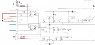
I bought this business model 8032 with a busted Screen Display and suspected that the unit was (maybe) left in a basement or damp space and maybe have been tinkered too as there was a monitor schematic that came with it. The board are somehow had some rusts on the sockets. So I disconnected the whole monitor assembly (hoping to connect it with a composite monitor if I can make it output a 15Khz (instead of the 20khz) by maybe using one of S.Gray's NTSC 15khz Edit ROM).
I have been scanning and reading some posts here in resurrecting 8032s and composite out (well aware of PETTESTER too ---had used one years ago which is a modified one for my PET2001-8 which I may have gotten from you (Daver2). Eventually I fixed my PET2001-8 and also used one of the first PETVET to replace my ROMS/RAMS)...but that is another story...still working up to now.

So for this 8032:
I have tried to restore the unit as is first (after cleaning with IPA, etc.) and switched it on as is....NO CHIRP but I have the voltages. Put it back on the shelf for future work.

LATEST STATUS
I have so far replaced all sockets (CPU,CRT,PIA and ROM plus CHAR rom). It used to be old white sockets. I have prevented any damage on the tracts by prying the old sockets and un-soldered each pins and pulled them out one by one. I have now replaced them with a better socket.
I have the following voltage readouts:
ON UA4 (MM5290J-4) which I think is a 4116 RAM equiv.
Pin 1 -4.89 volts
Pin 8 11.89 volts
Pin 9 4.82 volts

Voltage across the capacitor is 9.89 volts.

I have taken out the PIAs for now as I do the tests /repair. I have tried to create a 8032 Pettester but found out my last remaining 2716s do not test blanks after erase so I need to procure some eproms from China (non locally available).

Unfortunately the 4116 RAMS are socketed so I have no way of testing them. I have tested my 6502 cpu and have also tried a newly bought CRT chip...no success...no chip on power up.
I am getting ready for scoping the CPU next (as per an old regarding thread I am reading a dead 8032 repair conversations with Daver2, etc.)

I have used 2 Multimeters (Micronta and Fluke 112) and both readings are the same (+/-.....)
Thank you...will update next...hoping to have a PETTester soons as I just found another 2716 eprom.
Question: is the 2716 eprom (for Pettester and Edit ROM) plugged is compatible into the 24 pin socket? I want a confirmation as that it wht I understand.
 
Hi Riz,
Yes a 2716 can be used directly in the Edit socket. You can also use a 2816 EEPROM if that is easier to program with your burner.
 
Back
Top