• Please review our updated Terms and Rules here

Pet 8032090 universal board no chirp

anti77

Member
Joined
Oct 9, 2023
Messages
28
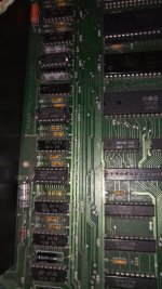
Finally have some time to work on a dead PET motherboard (no chirp on boot, no image on screen) that was laying around for about 20 years now.

It was missing the CPU, so just bought a 6502 from Aliexpress (it may be a fake but at least pins seems to match). It has good looking reset signal, and a nice 16mhz signal on UD2 pin 10. The 1 MHz clock looks nice on UE4/10 and UE4/8. Data and address lines look good on the scope on the CPU, nothing seems stuck.

As the motherboard had a Supersoft HR80 high resolution adapter, for now I'm trying without it, using a 901447-10 from a VIC20 in UA3, and the PETTESTE2KV04 on UD7. The PETTESTER is written 8 times on a MBM27128-30 EPROM and with an Open2327RomAdapter with 100K mounted on R#1 & R#2, short on R#3.
It seemed that the 74154 decoder was not working, so unsoldered it, but it's logic checked out a TL866ii. Now it's socketed.
I'm a bit lost around the ROM's chip selects, as I suspect some problems with the original roms (all soldered). Any ideas what should I check next? I would like to avoid start unsoldering IC's if it's not necessary...
 
Do some of the ROMs get *really* hot? If you think the PETTESTER should be running, do you have H / V drive signals on the video output? Best case your monitor brightness is turned down...
 
With a completely dead PET it is more useful to start with a NOP generator.

This can either be a 'socket sandwich' or a spare 6502 CPU with the data bus pins bent out and tied to 0V and VCC as appropriate to form a NOP instruction ($EA).

Dave
 
No ROMs getting hot, only the 6502 seems warm to the touch.

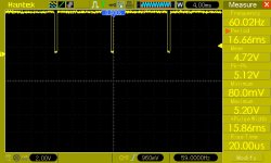
J7/5 horizontal signal looks:
pic_44_9.jpg
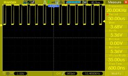
J7/3 vertical signal looks:
pic_44_8.jpg
No image on the CRT, but when I unplug J7, there is a very bright dot in the middle of the screen, so I don't want to leave it there for too long. Brightness should be on max...

Maybe I have a picture just that it's soo weak that I can't see it? :biggrin: It can even be board incompatibility with 9" or 12" monitor. The video signal on J7/1 also looks it does output something.

I'll sandwich some 40pin sockets for a NOP generator next.
 
Last edited:
Nevermind... It was r572/r573 in the CRT, probably from so many starts without being plugged in to the board.
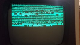
Seems like Pettester starts, now it's time for me to read the manual.

IMG_20240127_223523_8.jpg
 
Last edited:
No image on the CRT, but when I unplug J7, there is a very bright dot in the middle of the screen, so I don't want to leave it there for too long. Brightness should be on max...

Maybe I have a picture just that it's soo weak that I can't see it? :biggrin: It can even be board incompatibility with 9" or 12" monitor. The video signal on J7/1 also looks it does output something.

I'll sandwich some 40pin sockets for a NOP generator next.
No need to use a NOP generator if you have correct drive signals (and even video).

The reasoning is that if you have these drive signals you should see something on the screen and if not, the problem is the monitor or the connection to it.

Those resistors appear to fail frequently... good luck with the RAM test, can't help you there as I haven't had a RAM failure in any PET I've encountered (not a large sample size)
 
Nevermind... It was r572/r573 in the CRT

Did you mean R752 / R753? If those resistors have failed it is not a bad idea to also replace C753 even if replacing the two resistors (only) does get the monitor back up and running. I saw a recent case where the resistors soon failed again due to C753 breaking down under 'realistic' operating voltage, even though the capacitor seemed fine when checked with a meter before replacing the resistors. There is a similar case buried somewhere in these threads as well.
 
Sorry, yes, R752/753. Thanks for the tip, I'll replace C753 if the resistors fail again (thinking - if it ain't broke don't fix it).

By piggybacking managed to find faulty 4116s, so I've replaced UA11, UA15, much better looking but still not there:
VID_20240128_121236-ezgif.com-video-to-gif-converter.gif
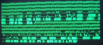
As Piggybacking won't help anymore, and if I understood the PETTESTER manual right, looking at the second 256 characters values (h,i,j,k so 011010xx) also D6,D5 and D3 are stuck high?

Note: scoping /RAS0 and /CAS0 seems right (not that I know how it should look :biggrin: ), however /CAS1 is flat. I assume it should be like that as PAGE0/1 testing is in the lower RAM only?

A replacements I'm using 41256s, with pin1 and 8 bent up, linked to pin16 and 9 respectively, hope you guys don't mind. 100ns, way less power consumed, but 3/4 of capacity lost.
 
Last edited:
I see patterns of 4 character strings repeating, but not consistently.

First off, I would check the refresh counter signals RAn on UE8 of schematic sheet 5. And also that UE8 is being enabled correctly on pins 1 and 19. RA1 should be 500 kHz. RA2 should have half the frequency of RA1 and so on down to RA7.

If possible, use your oscilloscope to see if the refresh signals are correctly being passed through UE8 to the DRAMs when UE8 pin 1 is LOW.

Dave
 
Thanks a lot for your help so far!

Down to 7.182Khz on RA7, as supposed to.

I had a feeling I need to change UA13 as well:
IMG_20240128_151348_5.jpg

So now PETTESTER is at 16K DRAM test, meaning the upper 16K is not detected. But it passed the ROM tests!

I still don't have a /CAS1 signal. I'm looking at the Master Timing schematics, around UD5. I have nothing on UE2/12 (so back to the 74LS157 MUX now).
 
Last edited:
Stop...

If you now have 16K detected the PETTESTER will have had a 'sneak look' at the top 16K, realised it is not working properly, and will not test it any further. Hence the reason you are not getting any /CAS1 pulses...

The next thing to do is to leave the DRAM test running for at least 20 full pass cycles...

Then, we need to swap over the two /CAS signals so that the upper 16K becomes the lower 16K. I will explain how to do this after the memory test has had a good run...

Dave
 
Test is running. Will take a while....

Please lt me guess, we'll cross over R11 and R10, switching /CAS0 with /CAS1? Will that switch the upper lower banks and we start over?
 
Test is running. Will take a while....

Please lt me guess, we'll cross over R11 and R10, switching /CAS0 with /CAS1? Will that switch the upper lower banks and we start over?
It sure will!

Your guess is right on the money...

It always takes a long while to test RAM. It is worth it though to give it a thorough test...

Dave
 
After switching R11/10, and replacing UE14, the 32KB DRAM test passed at least 0x20 times. I'm so happy! I've learned that PETSCII is not ASCII, thus managed to not replace more RAM chips than needed.

Thanks @daver2 , you do a great job helping the community here.

Before adding back the Supersoft HR80 high resolution adapter, I'm off to look for some alternative EDIT ROMs as I would like to add a ROM switch to use up fully the 27128's I have laying around!
 
Not sure what UE14 has to do with the RAM though...

Yes, PETSCII <> ASCII!

>>> Thanks @daver2 , you do a great job helping the community here.

No problem, I enjoy it...

Have you tried putting R10 and R11 back?

What pointed you at UE14?

Dave
 
Sorry, UA14, a 4116 DRAM, hard to see on the printed schematic.

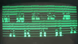
I saw something like this on the screen (was changing):
uuuu.jpeg

The clue was the first 4 characters read back, usually d,e,f,g (even if the photo shows d,e,n,g). When I realized the PETSCII "d" is 0x44 or 0b01000100, that seems a stuck D2 and D6. D2 is the first and UA14 is storing that since I've crossed R10/R11. These I left as such, so after a few years I'll really have to scratch my head why I've done this. :biggrin:

I have a bigger issue now, burnt an edit rom(not sure if the right one), there is chirp, it boots, but after a few seconds the cursor blink speed doubles up and accepts no keys anymore. I believe the 6520 PIA's are responsible, don't have a spare nor are they socketed, so for now I'm a bit stuck.
 
UA14 makes much more sense...

Actually, PETSCII 'd' is 0x04 (depending upon which character generator you have installed of course). A 'D' is 0x44.

The '@' is 0x00.

I see you have used a character generator in UA3 from a VIC20 and are now replacing the EDIT ROM. Can you explain why please?

What ROMs did/does the machine have?

Dave
 
Last edited:
Kernal UD6 - 901465-22
Basic UD8 - 901465-21
Basic UD9 - 901465-20
Basic UD10 - 901465-23
Char UB3 - 901447-10

For the edit ROM I've wrote edit-4-80-b-50Hz.901474-04-0283.bin

About the cursor, I've found that if I put my hand on the top of the 6502, blinking stops/slows. I can't know what actual cpu was this before the chinese faked it as a mos 6502, will look for anoriginal CPU's in some of the 1541 disk drives I have. Will have to search the metal cover that goes over the Clock circuit as well.
 
IMG_20240215_134210_0.jpg
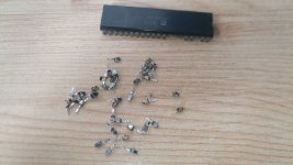
Replacing the CPU socket fixed all remaining issues... I remembered the original CPU I removed about 20yrs ago had the legs fall off. It's interesting that I still have that CPU now :biggrin:

Just look at that blue and black oxidation on the socket pins.
 
Last edited:
Back
Top