- VCF South West - June 14 - 16, Davidson-Gundy Alumni Center at University of Texas at Dallas
- VCF West - Aug 2 - 3, Computer History Museum, Mountain View, CA
- VCF Midwest - Sept 7 - 8 2024, Schaumburg, IL
- VCF SoCal - Mid February 2025, Location TBD, Southern CA
- VCF East - April 2025, Infoage Museum, Wall NJ
-
Please review our updated Terms and Rules here
You are using an out of date browser. It may not display this or other websites correctly.
You should upgrade or use an alternative browser.
You should upgrade or use an alternative browser.
Pet 8296D no signs of life
- Thread starter Desperado
- Start date
daver2
10k Member
Yep, that's a good start.
Don't forget the power rails...
Also, I assume you have found the service manual etc. at http://www.zimmers.net/anonftp/pub/cbm/schematics/computers/pet/8296/. How good is your German...
Dave
Don't forget the power rails...
Also, I assume you have found the service manual etc. at http://www.zimmers.net/anonftp/pub/cbm/schematics/computers/pet/8296/. How good is your German...
Dave
Desperado
Veteran Member
- Joined
- Nov 25, 2017
- Messages
- 6,827
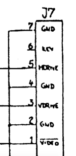
Good morning, I'm trying to measure the voltages on the J8 connector but I don't understand well the differences compared to the diagram ...
On the diagram J8 has 5 pins while the Pet connector j8 has only 4 and 1 is not connected .... how should I do to check the voltages?
On the diagram J8 has 5 pins while the Pet connector j8 has only 4 and 1 is not connected .... how should I do to check the voltages?
Attachments
eight088
Experienced Member
Desperado
Veteran Member
- Joined
- Nov 25, 2017
- Messages
- 6,827
Sorry I was wrong to attach the image ... the diagram of J8 is still different from my connectorThe schematic you have attached is J7 and you're looking at J8 on the motherboard. I've attached the schematic for the power supply, which has J8 on there.

eight088
Experienced Member
Oh yes I see. I think if you measured the voltage across the yellow wire and ground, that should be 5v. If this is true then I think the AC line would be good, because the ac line feeds the 7805 regulator via a diode and then the output goes to J8 pin 5.
Desperado
Veteran Member
- Joined
- Nov 25, 2017
- Messages
- 6,827
unfortunately I have not yet measured anything because I do not understand how to do it ....Oh yes I see. I think if you measured the voltage across the yellow wire and ground, that should be 5v. If this is true then I think the AC line would be good, because the ac line feeds the 7805 regulator via a diode and then the output goes to J8 pin 5.
eight088
Experienced Member
I'm not familiar with the 8296, but it looks like there is no 7805 regulator at VR1 or VR2? That seems strange when I look at the schematic. It might be best if you wait for someone else to help you.
eight088
Experienced Member
oh wait - you must have a switching power supply, hence no VR1 or VR2. That makes sense now. I think if you still measure the yellow wire to a ground point with your multimeter (red probe touching the metal clip on the yellow wire on the connector at J8) and then the black probe on a ground point on the motherboard it should read +5v (the blue wire will be ground)
Desperado
Veteran Member
- Joined
- Nov 25, 2017
- Messages
- 6,827
yes i have switching power supply!oh wait - you must have a switching power supply, hence no VR1 or VR2. That makes sense now. I think if you still measure the yellow wire to a ground point with your multimeter (red probe touching the metal clip on the yellow wire on the connector at J8) and then the black probe on a ground point on the motherboard it should read +5v
eight088
Experienced Member
that makes more sense now. So pin 1 isn't needed on J8 then, thats why you only have four pin connector. The notes where at the bottom of those schematics.yes i have switching power supply!
eight088
Experienced Member
Those numbers look goodOk i measured J8 connector (from power supply):
YELLOW= 4,98 V
ORANGE= 12,5 V
BLUE= 0V

daver2
10k Member
I concur, the DC voltages are fine. Good guidance @eight088.
So @Desperado, we have power, but no video signals at all. It is, therefore, not surprising that the monitor screen is black and that the initial fault is on the PET logic board.
So, what is your next step?
Dave
So @Desperado, we have power, but no video signals at all. It is, therefore, not surprising that the monitor screen is black and that the initial fault is on the PET logic board.
So, what is your next step?
Dave
Desperado
Veteran Member
- Joined
- Nov 25, 2017
- Messages
- 6,827
Cpu signals???I concur, the DC voltages are fine. Good guidance @eight088.
So @Desperado, we have power, but no video signals at all. It is, therefore, not surprising that the monitor screen is black and that the initial fault is on the PET logic board.
So, what is your next step?
Dave
daver2
10k Member
Spot on my friend!
So, which ones?
Dave
So, which ones?
Dave
Desperado
Veteran Member
- Joined
- Nov 25, 2017
- Messages
- 6,827
pin 40 - ResetSpot on my friend!
So, which ones?
Dave
pin 7 - Sync
pin 3-39-37
ok?
daver2
10k Member
Excellent.
I would add pins 4 and 6 to your mix as well.
Dave
I would add pins 4 and 6 to your mix as well.
Dave