• Please review our updated Terms and Rules here

Please help with 8050 drive...no comms with PET

Nama

Veteran Member
Joined
May 22, 2009
Messages
874
Location
New Zealand
Thought I'd post this here.
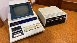
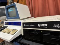
I have a 8050 drive that I'm restoring to work with my chiclet PET 2001 running BASIC 4.
After some cleaning and greasing of drives, reforming of caps, replacing a bad socked and fixing a broken leg on one of the ROMs, I now passes selftest. The drives briefly spin when a disk is inserted, and all voltages look good. So it looks good...but...

The problem I'm having is I can't seem to get the PET to talk with the drive.

Doing a PRINT DS$ just responds with READY with no response from the drive.

I have tested the IEEE cable and the PET with a PETSD+ drive emulator, and that all works fine.

Any help would be greatly appreciated.

Thanks
 

Attachments

  • 448698338_321159807732676_4610986754168057536_n.jpg
    448698338_321159807732676_4610986754168057536_n.jpg
    1.3 MB · Views: 2
Thanks Colin. Appreciate it.

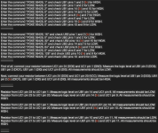
Hi Dave, I have spent the last hour or two working through all your tests from the above mentioned thread. My logic probe is dead so I'm using an old analog scope for the readings.
I have taken screen captures of the text file I was working with (see attached). You can see there that many pins don't read as 5v, they are marked in red and are reading just over 3v.
Apart from the low 3v, all seemed to test good (or at least the same as desperados results) until I got to UH2 pins 11, 12 and 13.

Desperado read:
11 low
12 high
13 low

I read:
11 High
12 Low
13 Low

And that's where I have paused for now.
Any advise would be greatly appreciated.

Philip
 

Attachments

  • Screenshot 2024-07-03 at 9.00.42 PM.png
    Screenshot 2024-07-03 at 9.00.42 PM.png
    1.2 MB · Views: 7
  • Screenshot 2024-07-03 at 9.00.54 PM.png
    Screenshot 2024-07-03 at 9.00.54 PM.png
    863.6 KB · Views: 7
  • Screenshot 2024-07-03 at 9.01.03 PM.png
    Screenshot 2024-07-03 at 9.01.03 PM.png
    322.1 KB · Views: 7
Ah, this was the 'problematic' gate - possibly an error on @Desperado's board between the schematic and the PCB. I wonder if (on your board) the 'error' has been corrected?

Can you measure the following please:

UJ2 pins 1, 2 and 3.
UH2 pins 1, 2 and 3.
UH2 pins 11,12 and 13.

And report the readings.

Just out of interest (regarding the low(ish) logic HIGH voltage level) you have checked the +5V rail haven't you? Also, can you check between random ICs directly across the 0V and +5V pins of the ICs (check the data sheets for the ICs for these pins) using a multimeter. I just want to rule out a power supply problem or excessive voltage drops across the PCB tracking.

Dave
 
Hi,
This is still with UE1 and UC1 still removed.

UJ2
Pin 1 - Low (but possibly floating as its about 0.5v ???)
Pin 2 - Low
Pin 3 - High (with a sawtooth ripple)

UH2
Pin 1 - Low
Pin 2 - 1.7v (floating ???)
Pin 3 - Low

UH2
Pin 11 - High (with a sawtooth ripple)
Pin 12 - Low
Pin 13 - Low

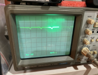
Poked around with a multimeter, and the 5V line is a little low overall, around 4.85v. Looking at it with the scope it is at exactly 5v but with a negative going sawtooth ripple. See attached.
 

Attachments

  • Screenshot 2024-07-03 at 10.19.13 PM.png
    Screenshot 2024-07-03 at 10.19.13 PM.png
    1.2 MB · Views: 3
Last edited:
So, 10 ms is 100 Hz.

I am guessing you are living in a country with a 50 Hz AC supply? Full-wave bridge rectified would give 100 Hz - which is what we are seeing. I suspect either:

1. The logic is drawing a high current from the +5V rail or (more likely)
2. The large DC smoothing capacitor(s) on the +5V rail are failing.

The logic readings that you provided look correct (I think this PCB matches the schematic)!

UJ2 pin 1 is (or should be floating). With a permanent LOW on UJ2 pin 2 input - the output (on UJ2 pin 3) should be permanently HIGH.

Is the sawtooth that you are seeing on UJ2 pin 3 a result of what you are observing on the +5V rail?

Dave
 
Yes, I'm in New Zealand, so our time zones will be quite out of sync.

Is the sawtooth that you are seeing on UJ2 pin 3 a result of what you are observing on the +5V rail?
Yes, it looks to be the same 'sawtooth' shape as the +5V rail.
Quite possible that the smoothing cap is indeed on its way out. I did try to reform them both, and I noticed as I was doing it that one cap acted quite different from the other. I may have a replacement cap that I got a few years back for my Pet, but never actually needed to install. I will look for it at some point and install.
Ok..off to work. If you have some more tests, then I will do some more poking around this evening.
Thanks again
 
I think I'll put UE1 and UC1 back in and try again to see if I can get the drive to respond to any commands.
 
Ok, some progress.
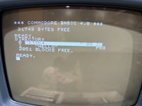
After some board inspection I have come to the realisation that the drive was modified as #9 not #8 as default. I have jumped the drive back to #8 and I can dow access the 8050!!!.
Still haven't been able to format a floppy successfully....but otherwise good news!!!!
 
Well done...

Yes, always good to document the configuration first. If nothing else, it helps you to put it back as you found it!

Never mind, you put some diagnostic skills to the test!

Dave
 
yes...I wasn't actually aware it has jumpers for changing the device number!
Both drives seem to read and write ok now, although it does seem fussy about the floppies I use, or maybe I just have some bad disks.
Thank you very very much for all your help. Will continue to test and report back if I have any issues.

Cheers again!
 
Yes, floppy disks deteriorate with time and you would need to use appropriate media - for example, no HD media (1.44MB).

Dave
 
Back
Top