• Please review our updated Terms and Rules here

Powering a PET 2001-N from a bench supply?

bitfixer

Veteran Member
Joined
Apr 6, 2011
Messages
679
Location
San Francisco, CA
Hello,
I wanted to see if it was possible to power a PET 2001-N board directly from a bench supply instead of going through the transformer/regulators. On this machine I was using a ROMulator to replace ram, so I first removed all the RAM on the board, which as far as I could tell was the only thing which required the +12 and -5 supply - but I may be wrong about that.
Then I connected GND and +5 from the supply onto the corresponding lines on the 6502. After turning on the supply, the 5v line was only at 3.7V and the supply was drawing about 500mA, and the reset signal was also at 3.7 and did not dip to GND at any point.

First guess is that somehow the unpowered 5v regulator and associated support components create a loading effect which makes the voltage dip, but I don't really understand. Fortunately the board works fine back with the transformer, so it doesn't look like I damaged anything.
Has anyone had luck powering a PET directly from a bench supply, bypassing the regulators? Thanks.
 
You are correct - an unpowered regulator will appear as a load :-(!

You can feed a regulated DC voltage into the AC inputs instead (obviously at a higher voltage) and use the PET on-board voltage regulators. That is the simplest way of doing it...

12V is used by the cassette interface if I remember correctly (well, perhaps the unregulated 9V supply).

Dave
 
The 2001N uses two +5V regulators to divide the load on the PET board. Did you hook up your new +5V to both circuits?

Daver is right, if you use a +9V supply into the full wave rectifier outputs, you will also supply power to the cassette motors.

So wire +9 VDC to J8 pins 2 and 4, and the power supply return to J8 pins 3 and 6. Note: Disconnect the J8 cable or the power supply will be across the huge C1 (23000 uF) capacitor. Of course disconnect the AC plug. The power supply should be current limited to about 1A or so I think.
 
Thanks both Daves, quick sanity check on the pin numbering for J8 - on the schematic I noticed the pin numbering is all over the place. I'm assuming that the pins are really sequential, and pin 1 should be on the opposite side as the key (pin 7), is that correct?
 
From the Zimmer's 2001N schematic it looks like J8 pin 2 should be +9V dc and J8 pin 3 should be 0V (from your bench power supply).

Look for CR3 on the main logic board and follow the PCB tracking from the anode and cathode back to the J8 power pins just to be doubly sure.

If your bench power supply has a current limit - then use it - just in case you forward bias CR3 by accident. This will avoid a costly mistake...

The +9V unregulated (taken off before the +5V regulators) is used by the cassette interface to drive the motor(s).

As far as I can also tell, the +12V and -5V is only used by the 4116 DRAM (that you have removed).

Keyway is J8 pin 7.

I always trace out anything related to power if I am making modifications (or testing) just to make sure the original equipment manufacturer (OEM) didn't inadvertently (or on purpose) introduce an error...

Dave
 
If I have any question about which pin is which, I always double check with an ohm meter. Sometimes documentation can be wrong. It is simple enough to ohm it out.
Dwight
 
Thanks all,
I gave it a try with my bench supply, connecting 9VDC to J8 pin 2, and the supply 0v to pin 3.
After switching on, the bench supply read about 0.5A, and checking the 5V rail, it was at something like 1.5V. Checking the voltage at pin 2 on J8 read about 4.5V.
Thought about this for a while and then took a more careful look at my bench supply. This particular one (HP 6236B) has a +/- up to 20V and + up to 6V circuit. The 20V side actually has a max current of 0.5A, and there is a short circuit foldback which limits the current. So that part makes sense, I guess it was lowering the voltage to limit the current, and which means it's not capable of powering the PET directly in that way.
I also tried running +6V to pin 2, thinking that we might still get 5V out of the regulators, but this time it went up to 1.0A and got stuck there. A little confusing since the supply says it can do up to 2.5A up to 6V, but according to the manual for the supply there is short circuit protection which limits to 1.0A. So I'm not really sure how you get it to supply more than that.
In any case, I stopped testing at this point. The board still works with the transformer which is good, and now looks like I just don't have a bench supply capable of powering it directly. I'll revisit this at some point if I have another power supply at my disposal.
 
Forgot to mention when trying the 6v case, result was similar, the 5V line was a low voltage and pin 2 on J8 was something around 4v.
 
On the older chicklet PETs, you can feed the +5V regulators 9V on pin 2 directly, bypassing the rectifiers.
Unfortunately, on the 2001-N, the -5V and 12V complicate things.
However, you might be able to back-feed 9V, -9V and 16V DC on J10 and J11 where the unregulated voltages are presented.
That won't bypass the regulators, but you get the transformer and the rectifiers out of the way.
If you don't need -5 and 12, you can just connect 9V to pin 2, since it's disconnected from the rectifiers when the connector is unplugged.

Also note, your supply will probably need 3amps of current or more. The LM-340-5 is rated at 1.5A and there are two of them.
IIRC, the regulators need at least 3V more than the regulated output so 8V minimum.


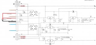
320349-9(2).jpg - 2001-N PSU Schematic
 
Last edited:
Yes, I agree with Hutch.

The OP doesn't require the +12V and -5V rails as the DRAM has been removed and replaced by one of the CPU/RAM boards.

Agreed that you need at least 7.5V (better 8.0V) at the input to the regulators, so 6V is too low.

I suspect (as you do) that the PSU is current limiting and is not ‘man enough’ for the job in hand.

I suspect your power supply should deliver up to the specified current; but, if the current draw tries to exceed the limit, it may be ‘folded back’ and limited to the stated 1A. This accounts for why the rated output current is higher than the limit.

Your 6V output is too low (from the Voltage perspective) and the 20V output is too low (from a current perspective). Although I haven’t read the manual for your particular PSU...

Dave
 
FWIW, I measured the current on one leg of the AC input (pin 1) using an inductive current clamp and read ~1.4 AMPs on my 2001-32N, with all the RAM still installed.
The Killawatt read ~0.5A on the mains power cord.
When I measured the DC current on my VIC-20 with the original linear regulator I had 2.3 AMPs
 
The 6V output from your power supply can supply the requisite current, but not the voltage required to adequately operate the PETs voltage regulators.

The 20V output from your power supply can't supply the requisite current.

The simple answer is that you can't drive a PET with that power supply unit.

Dave
 
Interesting, thanks for the information. I somehow had the impression that my supply was much beefier than it really is, too bad.
I may try it on one of the original 2001 boards I have, bypassing the regulators. Also occurred to me that removing the regulators might be an option, but that was far too destructive for my taste.
 
I decided it was time to get a more capable power supply for the bench. Tried powering the 2001-N from the supply again, this time with success. 9VDC on pin 2, GND on pin 3. Had to adjust the current limiting on the new supply, but once it allowed above 1.6A or so, it worked. Also working connected to an RGBtoHDMI, so now I have a PET board that can run autonomous of its chassis - very nice.
 
Back
Top