• Please review our updated Terms and Rules here

PS/1

Gary C

Veteran Member
Joined
May 26, 2018
Messages
2,318
Location
Lancashire, UK
Does anyone have schematics of the 2121 Ps/1 monitor circuit diagram.

Search online has been a little fruitless.
 
So it doesn't look like the monitor circuit diagram is available:(

The vertical scan has failed so I'm just getting a bright line. This monitor also seems to have some encapsulated components so if they have failed I have no idea what they are.

So its going to be difficult.

Probably try to identify amp transistors and test them first.
 
Following the circuit through, the vertical sync goes to a LA7851 which appears to generate a ramp that is synced to the vertical sync pulse.

So possibly a transitor drive. Testing the bigger transistors, I note that a transistor is showing a dead short across the base & emitter. Taking it out of circuit, it shows a healthy junction from collector to base but no conduction from base to emitter, however the PCB still shows a short between the base & emitter connections.

The base comes from a small pcb mount transformer that is showing a direct short between the two terminals, so it looks as if this has failed.

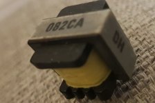
Problem is, it has 082CA DH written on it, but I cant find any reference to it.


082CA.jpg

Might have to open it up and unwind :(
 
Last edited:
Its not the main transformer (this is about the size of your thumb) and I think I am going to have to unwind it.
 
Does it connect to the port that would goto the pc? Pics of placement on the pcb would help more.
 
Its in the CRT vertical deflection circuit.

There is a large power transistor that drives the vertical yoke, and the secondary coil of this transformer sits between the base and earth. Obviously the signal from the ramp generator must go through the primary. The primary is showing about 20 ohm which is about right, but the secondary is showing 0 ohm (and the meter is capable of reading down to 0.01 ohm) and the power transistor is not showing a good PN junction between base and emitter which suggests that one of them failed and took out the other.

Need to get the turns ratio approx the same to have the right size of signal and without a match, I think I am going to have to unwind it.


The supply to the PC is fine, the horizontal scan is fine, its just that the monitor draws a single line across the display meaning the vertical deflection circuit isn't driving.
 
Last edited:
First thing I do is poke around the yoke for shorts or bad joints... Have you tried doing that with a plastic rod while the monitor is on? Just poke round till something happens lol.
 
Well confused

The LA7851 has a vertical oscillator and ramp generator that outputs the signal on pin 15, however pin 15 isn't connected to anything !

Its not like its not used as the vertical hold and size are wired to this chip as the example shows, it just seems to ignore the output :(

Hummm.
 
It appears that there is some encapsulated circuits that appear to control the multisync nature of this monitor and without a drawing and without the realistic chance of replacing them, this fault will now take back stage while I look at my Hazeltine monitor for which I have a much more realistic chance of fixing.

Ah well :(
 
Generally speaking, the horizontal, not vertical, output transistor is driven by a small transformer. Its ratio is typically in the order of 10:1 and its short secondary winding feeds the base & emitter terminals of the horizontal output transistor, so if you check these on a meter, they will measure like a dead short which is normal. The small transformer that you have shown is much more likely part of the horizontal scan stages than the vertical scan stages.

The vertical scan stage architecture, be it IC based, or discrete transistors, is normally much easier to fault find than the horizontal. Really it is just a power amplifier, not dissimilar to an audio power amplifier, amplifying a sawtooth drive wave to feed the vertical scan yoke coils.

Sometimes, a manufacturer will use a scan IC, just for its sync separator & oscillator sections, and rather than using the IC's internal power output stage, feed the sawtooth signal to a separate transistor based output stage. That could possibly explain why the output of that IC, on pin 15, appeared to be not connected. I will look up that IC.....
looking at the data sheet, they may well have taken the vertical ramp signal from pin 16, to feed a different type of output stage than the one shown on the schematic. This IC contains the oscillators for both the H & V scan.


As can be seem from their example schematic, the yoke's current is sampled by the voltage developed across the 4.7R resistor, this is fed back, from the output stage driving the yoke to pin 16, via the size control, so when all was working, there would be an approximate sawtooth wave on pin 16. But it would pay to check pin 15 again just in case there is a track connected to it under the IC that is hard to see, if it is a multi layer pcb. From what I can see with this IC it would be likely they used pin 15.

In any case, rather than just stabbing in the dark, the better method is to get the IC data sheet, and example circuit there as a guide, and then start to draw out the schematic from the pcb. The modules probably won't be a problem because it will likely be self explanatory what they are supposed to be doing when the schematic is drawn out and they could be re-generated as discrete parts. Often "modules" were used for the Vertical sync pulse integrator and there were just a string of resistors and capacitors to ground to make an LPF.
 
Last edited:
Cheers.

To be fair I haven't been just stabbing in the dark but trying to follow the circuit.

Its a bit of a pain as I really need to remove the board to fully see it.

As its a multisync monitor, it has three pots for trimming the different modes vertical size, selected digitally. This seems to complicate the circuit somewhat and the potted modules are not just resistor networks and you can see they contain IC's.

When I get more time, I think your right, that I need to get the pen and paper out.
 
Ah ha, scratched away the writing on the board to see where the traces go and LA7851 finally worked out it is connected to a LA7838 to drive the vertical and in this configuration, pin 15 of the 51 isn't used.

So time to do some testing on the LA7838 before ordering a new one.
 
tested and discovered nothing at the supply for the horizontal drive. This in turn comes from a MC7815C regulator. Line to the IC has one capacitor on it and its a dead short ! As its after a current limiting 3ohm resistor the regulator should be ok,

Replacement found in my bag of spares, replaced and now I have the vertical scan back !

Yes, very happy.

Havent tested it yet as I need to reconnect the video and PS/1 supply cables but its looking good.
 
Last edited:
Just a thank you to Hugo and Chuck for there help with diagnosing various monitor problems over the last 6 months. Even without a circuit diagram, recent learning helped identifying a fault that I didn't manage to resolve almost a year ago.
 
So

Dug out the keyboard and it doesn't work. Seems to have ingested a cup of finest Vinyl Matte paint, Magnolia no less which has damaged the membrane.

I can redraw with a silver pen but Unicomp seem to do replacements. Anyone used them ?
 
Well Unicomp was a blowout. Despite the website saying they stocked the membrane and taking the money for it, they dont have them. At least they refunded the money quickly.

So, the damage to the membrane is quite bad. One corner, the traces are completely missing.

I can try a silver pen, but does anyone have any better ideas ?
 
So a pen is great for remaking tracks, but not so good for remaking the pads. Its too lumpy and bridges the gap between top and bottom pads.

Next I will attempt to remake the pads with thin foil, have some very thin copper which might be a problem for long term use but it will prove the concept.
 
I used a nickel conductive pen from MG chemicals and I am scratching it away from the pad areas and quite pleased how well it adhered to the plastic. Where there are holes in the separating membrane, I have replaced the pad areas with some copper self adhesive tape (www.amazon.co.uk/dp/B0CH7VPQ2X?) and that seems to do the trick

Need to reassemble before final testing
 
Back
Top