Joerg Hoppe
Experienced Member
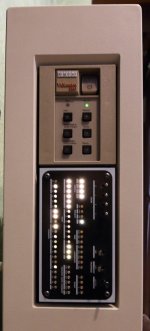
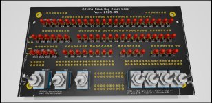
Guys,There is now an updated QProbe 2023 that adds disk drive activity to the display panel. I
FYI: as Mark told, the new drive LEDs can be driven by both the BA23 panel connector and QBone simultaneously.
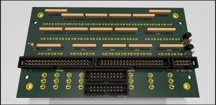
The BA23 20pin panel cable is routed throught the QProbe LED panel.
So if you like, you can wire up a BA23-QBone-QProbe combo.
And as Mark is happy now, I declare the endless prototyping phase as completed ;-)
Joerg
")