Upcoming Events:
- VCF South West - June 14 - 16, Davidson-Gundy Alumni Center at University of Texas at Dallas
- VCF West - Aug 2 - 3, Computer History Museum, Mountain View, CA
- VCF Midwest - Sept 7 - 8 2024, Schaumburg, IL
- VCF SoCal - Mid February 2025, Location TBD, Southern CA
- VCF East - April 2025, Infoage Museum, Wall NJ
-
Please review our updated Terms and Rules here
You are using an out of date browser. It may not display this or other websites correctly.
You should upgrade or use an alternative browser.
You should upgrade or use an alternative browser.
Rainbow 100B Memory extension board
- Thread starter na103
- Start date
na103
Experienced Member
na103
Experienced Member
na103
Experienced Member
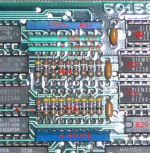
Hi, I just found a paper copy of the original circuit diagram of a 5415961-0-1 Rev A module
It has all the diagrams, all parts listed, but no PCB traces picture is included
I do not now if this document already exists on the web ?
I have no A3 Scanner, so I would need to find someone who can scan this
It has all the diagrams, all parts listed, but no PCB traces picture is included
I do not now if this document already exists on the web ?
I have no A3 Scanner, so I would need to find someone who can scan this
na103
Experienced Member
Hi, I just found a paper copy of the original circuit diagram of a 5415961-0-1 Rev A module
It has all the diagrams, all parts listed, but no PCB traces picture is included
I do not now if this document already exists on the web ?
I have no A3 Scanner, so I would need to find someone who can scan this
in the last few weeks I have searched everywhere but have not seen these.
it's gold! post some pictures here with your smartphone. I can verify my work before building the card
thank you
na103
Experienced Member
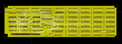
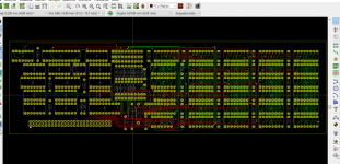
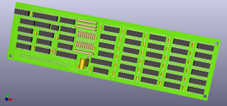
I share my work, as is and not tested, under CC-PD license
Gerber file and E7 GAL22V10 jed file which replaces the original bipolar prom
Gerber file and E7 GAL22V10 jed file which replaces the original bipolar prom
na103
Experienced Member
na103
Experienced Member
na103
Experienced Member
na103
Experienced Member
na103
Experienced Member
na103
Experienced Member
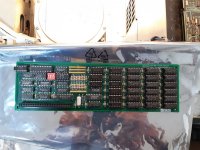
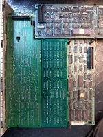
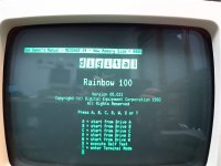
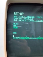
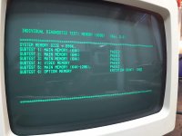
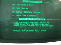
I finished the test with the different configuration, bank population, 64kb dram chip and dip setting.
Everything works perfectly!
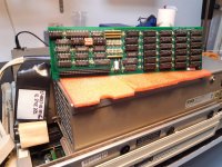
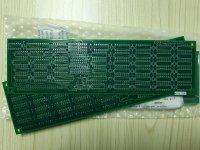
I thank VCFED and the users who sent photos and schematics of the board.
below the list of passive and active components.
the Mouser part number is only present for the components I purchased, the other parts are recycled from other old boards.
passive component:
active component
Everything works perfectly!

I thank VCFED and the users who sent photos and schematics of the board.
below the list of passive and active components.
the Mouser part number is only present for the components I purchased, the other parts are recycled from other old boards.
passive component:
| pos. | qt. | desc. | Mouser part. |
| C1 - C27 | 27 | 220 nF (0.22 uF) 50V +80-20% Z5U CER | C430C224Z5U5TA |
| FB1 | 1 | Bead Ferrite 0.1380DX 0.330LG | 2743002112 |
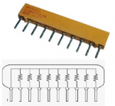
| RN4 | 1 | R network 9-470 2.0% 10 pin | 4610X-101-471LF |
| RN3 RN2 | 2 | R network 9-1.0k 2.0% 10 pin | 4610X-101-102LF |
| RN1 | 1 | R network 9-4.7k 2.0% 10 pin | 4610X-AP1-472LF |
| R10 - R17 R19 | 9 | 39 0.25W 5.0% | CFR-25JB-52-39R |
| R18 | 1 | 100 0.25W 5.0% | CFR-25JT-52-100R |
| R1 - R9 | 9 | 47 0.25W 5.0% | CFR-25JB-52-47R |
| SW1 | 1 | Switch DIP 4POS/SPST 30VDC 50MA | |
| C33 | 1 | 10uF 35v +75-10% axial AL EL | MAL213831109E3 |
| C28 - C32 | 5 | 47nf (0.047 uF) 50V +80-20% CER | C410C473Z5U5TA |
| C34 C35 | 2 | 10nF (0.01 uF) 50V +80-20% Z5U CER | C410C103Z5U5TA |
| J1 | 1 | 025X025 REC 2X30P | 5-102766-4 |
| 27 | 16 PIN DRAM SOCKET | ||
| 1 | 24 PIN U7 GALV22V10 |
active component
| pos. | qt. | desc. | Mouser part. |
| E14 E8 E15 | 3 | SN74S03N | |
| E16 | 1 | SN74LS00N | |
| E24 E23 | 2 | SN74S258N | |
| E32 | 1 | SN74LS27N | |
| E40 | 1 | SN74LS74AN | |
| E7 | 1 | GAL22V10D | ATF22V10C-15PU |
| E31 E39 | 2 | SN74LS04N | |
| E22 | 1 | DM74LS125AN | |
| E30 | 1 | SN74LS393N | |
| E38 | 1 | SN74LS244N | |
| E29 | 1 | SN74S280N | |
| E37 | 1 | SN74LS245N | |
| E45 | 1 | SN74S32N | |
| 27 | DRAM CHIP 41256 or 4164 150ns or better |

