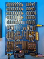
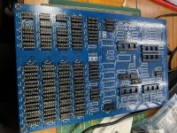
Just bios, monitor, and pal code there.Have you checked in here to see if what you're looking for is present?
- Alex
Upcoming Events:
| VCF West | Aug 01 - 02 2025, | CHM, Mountain View, CA |
| VCF Midwest | Sep 13 - 14 2025, | Schaumburg, IL |
| VCF Montreal | Jan 24 - 25, 2026, | RMC Saint Jean, Montreal, Canada |
| VCF SoCal | Feb 14 - 15, 2026, | Hotel Fera, Orange CA |
| VCF Southwest | May 29 - 31, 2026, | Westin Dallas Fort Worth Airport |
| VCF Southeast | June, 2026 | Atlanta, GA |
-
Please review our updated Terms and Rules here
You are using an out of date browser. It may not display this or other websites correctly.
You should upgrade or use an alternative browser.
You should upgrade or use an alternative browser.
Recreating the Ferguson Big Board
- Thread starter hideehoo
- Start date
hideehoo
Experienced Member
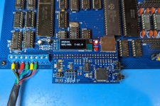
Speaking of floppies...finished up my custom Flash Floppy compatible PCB that plugs directly into the the Big Board's floppy port last night. Details on how to build your own are at https://github.com/djtersteegc/OpenFlops-Ferguson and also linked in the main reproduction repo's README. Now that I've reduced my workbench clutter (sounds like a good excuse) when using these boards, I can finally build and release the v1.1 board design. 

hideehoo
Experienced Member
Could you please send me a message? I have a few eprom questions for an mc68hc711Sure looks like the SWP board. If so, it should be supported by the "SmartROM" by MICROCode Consulting, https://www.microcodeconsulting.com/z80/smartrom.htm
I can copy/duplicate the PROM and one of those cute TTL testers should identify the IC's (or confirm they are the same as Enrico's pic). I about 10 spare FD1791's here too which should be 8876A compatible.
Finding bios source might be a bit tougher!
gekaufman
Experienced Member
Curious if you've had time to build up the revised board?
mcguire
Experienced Member
Hey, got any of those OpenFlops-Ferguson boards left? I'd like to have one for my beloved BigBoard.
(Disclosure: this is for me personally, not for LSSM)
-Dave McGuire, LSSM
(Disclosure: this is for me personally, not for LSSM)
-Dave McGuire, LSSM
mcguire
Experienced Member
Nevermind that request, I've made a few changes to the PCB layout (mainly to replace the unobtainium SD card socket) and am ordering some. Thanks anyway, though.
-Dave McGuire, LSSM
-Dave McGuire, LSSM
mcguire
Experienced Member
Alex, I didn't know you had a Big Board! Awesome!
-Dave
-Dave
gekaufman
Experienced Member
I just completed building up the V1.1 board. It works perfectly, and came up on the first try!@hideehoo it was great talking to you at VCF MW, again.
Have you had time to update the BoM for the v1.1 board? I picked one up from you there, and would like to start ordering parts.
Thanks!
- Alex
All the patches needed for V1.0 have been corrected.
No real part changes from the V1.0 for 2.5mhz.
For 4mhz, you won't need U97 and you'll need a 16mhz xtal instead of 20mhz as well as "A" speed parts and a 2716-1 for PFM3.3
The original Big Board docs are fine as a guide, just note the addition of 2 jumper blocks (JB7/8) and the solder jumpers on the underside to select 2.5 or 4mhz.
Thanks again to Chris for making this available. Ignore the messy workspace
- Gary
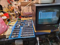
Thanks @gekaufman . I went with 28c16s for my ROMs.
As expected, Unicorn electronics was a great source for all the 74-series logic. I eventually plan to attach my board to a HH 8” drive, as the original might well have been, but I am also building the OpenFlops board, in the meantime. The Artery MCU (and programmer) was actually the hardest part to track down, and I had to order both from China via eBay, unfortunately. In retrospect, I probably should just have ordered the PCB from JLC and had them program and solder the Artery MCU, saving me some money.
- Alex
mcguire
Experienced Member
Thanks @gekaufman . I went with 28c16s for my ROMs.
As expected, Unicorn electronics was a great source for all the 74-series logic. I eventually plan to attach my board to a HH 8” drive, as the original might well have been, but I am also building the OpenFlops board, in the meantime. The Artery MCU (and programmer) was actually the hardest part to track down, and I had to order both from China via eBay, unfortunately. In retrospect, I probably should just have ordered the PCB from JLC and had them program and solder the Artery MCU, saving me some money.
Can you post a pointer to the MCU and programmer that you picked up?
Thanks,
-Dave
Dave,
Sure!
I bought an Artery AT-LINK+ from this eBay auction. The MCU I purchased is an Artery AT32F435RGT7 from this AliExpress seller, sorry for the earlier error.
I dunno how many Artery MCUs I'm going to program, so the programmer may be a waste of money. I do buy Gotek drives with Artery MCUs to run FlashFloppy on, so hopefully I'll need it at some point.
If anyone is interested, I can post my BoM for the board.
- Alex
gekaufman
Experienced Member
Looks like you're making good progress!
I'd bring up the board first, you can always swap them later. I suspect once they have chip's inserted they'll not show much.
I tend to use the machine pin sockets from China, which are actually surprisingly decent.
I'd bring up the board first, you can always swap them later. I suspect once they have chip's inserted they'll not show much.
I tend to use the machine pin sockets from China, which are actually surprisingly decent.
I finished soldering the resistors, transistors and headers tonight. Now just have the capacitors, and one bloody resistor network (that I forgot to order, and can't get locally) to do before I can clean the board and test for shorts.
I'm not happy with the EPROM and 20-pin 300 mil sockets that Unicorn sent. Everything else was good, but these look like crap single-wipe sockets to me. I'm tempted to replace them with pin strips, like I did for U88 and U109.
Honestly, given the low price of those pin strips, I'm always tempted to entirely forgo sockets and just use them. It's pretty darned easy to get them nice and straight if you keep a socket of the right size around to hold them parallel while you solder.
(photo after I soldered on the caps)
- Alex
View attachment IMG_0124.jpeg
Last edited:
I have also updated the BoM that @hideehoo provided, including where I sourced components from and what the power pins are, for verification of ICs:
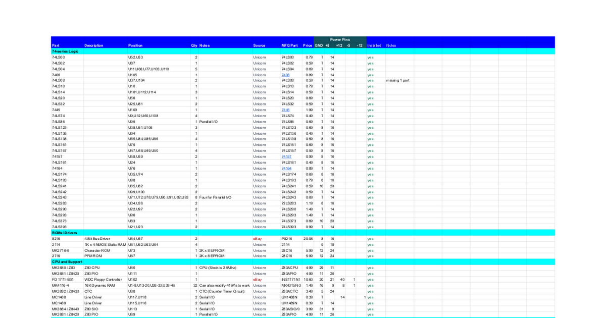
 docs.google.com
I've finished attaching all components to the board, and I've checked all the power rails to the RAM. I'll finish checking everything else this weekend, and since the PSU module and cabling is done, as well, might get to a first power up by tomorrow.
- Alex
Ferguson Big Board Recreation BOM
I've finished attaching all components to the board, and I've checked all the power rails to the RAM. I'll finish checking everything else this weekend, and since the PSU module and cabling is done, as well, might get to a first power up by tomorrow.
- Alex
Last edited:

